Feng Fu
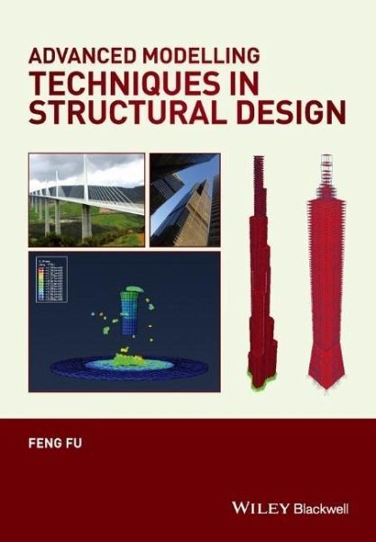
Advanced Modelling Techniques in Structural Design
Feng Fu
Advanced Modelling Techniques in Structural Design
- Gebundenes Buch
- Merkliste
- Auf die Merkliste
- Bewerten Bewerten
- Teilen
- Produkt teilen
- Produkterinnerung
- Produkterinnerung
The successful design and construction of iconic new buildings relies on a range of advanced technologies, in particular on advanced modelling techniques. In response to the increasingly complex buildings demanded by clients and architects, structural engineers have developed a range of sophisticated modelling software to carry out the necessary structural analysis and design work.
Advanced Modelling Techniques in Structural Design introduces numerical analysis methods to both students and design practitioners. It illustrates the modelling techniques used to solve structural design…mehr
Andere Kunden interessierten sich auch für
- Gang LiTheory of Nonlinear Structural Analysis190,99 €
- Gouqiang LiAdvanced Analysis and Design of Steel Frames191,99 €
- Andrew K. ChanComputational Geomechanics142,99 €
- David EtheridgeNatural Ventilation of Buildings153,99 €
- You-Lin XuWind Effects on Cable-Supported Bridges247,99 €
- Matthias BeckhHyperbolic Structures97,99 €
- Robert T RatayStructural Condition Assessment227,99 €
-
-
-
The successful design and construction of iconic new buildings relies on a range of advanced technologies, in particular on advanced modelling techniques. In response to the increasingly complex buildings demanded by clients and architects, structural engineers have developed a range of sophisticated modelling software to carry out the necessary structural analysis and design work.
Advanced Modelling Techniques in Structural Design introduces numerical analysis methods to both students and design practitioners. It illustrates the modelling techniques used to solve structural design problems, covering most of the issues that an engineer might face, including lateral stability design of tall buildings; earthquake; progressive collapse; fire, blast and vibration analysis; non-linear geometric analysis and buckling analysis . Resolution of these design problems are demonstrated using a range of prestigious projects around the world, including the Buji Khalifa; Willis Towers; Taipei 101; the Gherkin; Millennium Bridge; Millau viaduct and the Forth Bridge, illustrating the practical steps required to begin a modelling exercise and showing how to select appropriate software tools to address specific design problems.
Hinweis: Dieser Artikel kann nur an eine deutsche Lieferadresse ausgeliefert werden.
Advanced Modelling Techniques in Structural Design introduces numerical analysis methods to both students and design practitioners. It illustrates the modelling techniques used to solve structural design problems, covering most of the issues that an engineer might face, including lateral stability design of tall buildings; earthquake; progressive collapse; fire, blast and vibration analysis; non-linear geometric analysis and buckling analysis . Resolution of these design problems are demonstrated using a range of prestigious projects around the world, including the Buji Khalifa; Willis Towers; Taipei 101; the Gherkin; Millennium Bridge; Millau viaduct and the Forth Bridge, illustrating the practical steps required to begin a modelling exercise and showing how to select appropriate software tools to address specific design problems.
Hinweis: Dieser Artikel kann nur an eine deutsche Lieferadresse ausgeliefert werden.
Produktdetails
- Produktdetails
- Verlag: Wiley & Sons
- 1. Auflage
- Seitenzahl: 288
- Erscheinungstermin: 15. Juni 2015
- Englisch
- Abmessung: 246mm x 170mm x 18mm
- Gewicht: 680g
- ISBN-13: 9781118825433
- ISBN-10: 1118825438
- Artikelnr.: 42025911
- Herstellerkennzeichnung
- Produktsicherheitsverantwortliche/r
- Europaallee 1
- 36244 Bad Hersfeld
- gpsr@libri.de
Dr Feng Fu is a Chartered Structural Engineer and Member of the American Society of Civil Engineering. He received his PhD from the University of Leeds and MBA from the University of Manchester, and is currently a Lecturer in Structural Engineering at City University London. Prior to his academic career, he worked for several leading engineering consultants including WSP Group Ltd London, Waterman Group Ltd London and the Beijing Institute of Architectural Design and Research. He has worked with several world-leading architects on the design and analysis of a range of complex and challenging structures, as well as gaining extensive experience in designing buildings under extreme loads such as blast and fire.
About the Author xi
Preface xiii
Acknowledgements xv
1 Introduction 1
1.1 Aims and scope 1
1.2 Main structural design problems 2
1.3 Introduction of finite element method 3
1.3.1 Finite element methods 3
1.3.2 Finite element types 4
1.4 Conclusion 8
References 8
2 Major modelling programs and building information modelling (BIM) 9
2.1 Fundamentals of analysis programs 9
2.1.1 Selection of correct analysis packages 9
2.1.2 Basic analysis procedures 10
2.2 Building information modelling (BIM) 10
2.3 Main analysis programs in current design practice 11
2.3.1 Abaqus® 11
2.3.2 ANSYS 12
2.3.3 SAP2000 12
2.3.4 ETABS 12
2.3.5 Autodesk robot structural analysis professional 13
2.3.6 STAAD.Pro 13
2.4 Major draughting program 13
2.4.1 AutoCAD 14
2.4.2 Autodesk Revit 14
2.4.3 Rhino3D 14
2.4.4 Bentley MicroStation 15
2.5 Method to model complex geometry 15
2.5.1 Import geometry into SAP 2000 16
2.5.2 Import geometry into ETABS 19
2.5.3 Import geometry into Abaqus® 21
2.5.4 Set up model with Revit 25
References 25
Software and manuals 25
3 Tall buildings 26
3.1 Introduction 26
3.2 Structural systems of tall buildings 26
3.2.1 Gravity load resisting systems 26
3.2.2 Lateral load resisting systems 27
3.3 Lateral resisting systems and modelling examples 27
3.3.1 Moment resisting frames (MRF) 27
3.3.2 Shear walls 28
3.3.3 Bracing systems 28
3.3.4 Outrigger structures 29
3.3.5 Tube structures and modelling example of the Willis Towers 30
3.3.6 Diagrid structures and modelling example of the Gherkin 34
3.3.7 Super frame (mega frame) structures and modelling example 45
3.4 Modelling example of the Burj Khalifa 45
3.4.1 Model set up 49
3.4.2 Analysis and result 54
3.5 Modelling example of Taipei 101 with tuned mass damper (TMD) 55
3.5.1 TMD modelling 55
3.5.2 TMD modelling result 60
3.6 Conclusion 60
References 60
4 Earthquake analysis of buildings 61
4.1 Introduction 61
4.2 Basic earthquake knowledge 61
4.2.1 Categories of earthquake waves 61
4.2.2 Measurement of earthquake 62
4.3 Basic dynamic knowledge 62
4.3.1 SDOF 62
4.3.2 SDOF under earthquake 63
4.3.3 MDOF under earthquake 66
4.3.4 Response spectrum 67
4.3.5 Modal analysis 68
4.3.6 Response spectrum from Eurocode 8 68
4.3.7 Ductility and modified response spectrum 69
4.4 Modelling example of the response spectrum analysis using SAP20001 70
4.5 Time history analysis and modelling example using SAP2000 81
4.5.1 Fundamentals of time history analysis 81
4.5.2 Modelling example of time history analysis using SAP2000 81
4.6 Push-over analysis and modelling example using SAP2000 87
4.6.1 Introduction 87
4.6.2 Modelling example of push-over analysis using SAP2000 88
References 97
Codes and building regulations 97
Software and manuals 97
5 Progressive collapse analysis 98
5.1 Introduction 98
5.2 Design guidance for progressive collapse analysis 98
5.3 Risk assessment 99
5.4 Design and analysis method 99
5.4.1 Indirect design method 99
5.4.2 Direct design method 100
5.4.3 Selection of design method 101
5.4.4 Structural analysis procedures and acceptance criteria 101
5.5 Modelling example of progressive collapse analysis using SAP2000 -
nonlinear dynamic procedure 104
References 112
Codes and building regulations 112
6 Blast and impact loading 113
6.1 Introduction 113
6.2 Fundamentals of blast loading 113
6.2.1 Basic design principles 113
6.2.2 Major blast attack regimes 114
6.2.3 Blast load characteristics 114
6.2.4 Principle of the scaling law 114
6.2.5 Simplification of the blast load profile 115
6.2.6 Material behaviours at high strain-rate 116
6.2.7 Dynamic response and pressure impulse diagrams 116
6.3 Introduction of SPH theory 117
6.4 Modelling examples of impact loading analysis using the coupled SPH and
FEA method in Abaqus® 119
6.4.1 Modelling technique 119
6.4.2 Modelling example 120
References 139
Codes and building regulations 139
Software and manuals 139
7 Structural fire analysis 140
7.1 Introduction 140
7.2 Basic knowledge of heat transfer 140
7.3 Fire development process 141
7.4 Fire protection method 142
7.4.1 Active system control 142
7.4.2 Passive system control 143
7.5 Fire temperature curve 143
7.6 Determination of the thermal response of structural members 145
7.7 Structural fire design 145
7.7.1 Fire safety design objectives 145
7.7.2 Fire safety design framework 146
7.8 Major modelling techniques for structural fire analysis 146
7.8.1 Zone model 146
7.8.2 CFD model 146
7.8.3 Finite element method using the fire temperature curve 147
7.9 Modelling example of heat transfer analysis using Abaqus® 147
7.9.1 Model set up 147
7.9.2 Define the heat transferring parameters 152
7.9.3 Analysis 164
7.9.4 Model results 164
7.9.5 Other type of slabs 164
References 166
Building codes and regulations 166
8 Space structures 167
8.1 Introduction 167
8.2 Type of space structures 167
8.2.1 Double layer grids 167
8.2.2 Latticed shell structures 168
8.2.3 Tensegrity domes 170
8.3 Design load 172
8.3.1 Dead load 172
8.3.2 Live load 173
8.3.3 Temperature effect 173
8.4 Stability analysis of space structures 173
8.4.1 Member buckling analysis 173
8.4.2 Local buckling analysis 174
8.4.3 Global buckling analysis 175
8.5 Modelling example of a single layer dome using SAP 2000 (including
global buckling analysis) 176
8.5.1 Set up a 3D model in AutoCAD 177
8.5.2 Import the 3D model into SAP 2000 177
8.5.3 Define load pattern 177
8.5.4 Define load cases (including global buckling analysis) 177
8.5.5 Run global buckling analysis 180
8.5.6 Define load combination 183
8.5.7 Analysis and result 183
8.5.8 Auto-design module 185
8.6 Nonlinear geometric analysis of Tensegrity structures 185
8.6.1 The initial geometrical equilibrium (form finding) 185
8.6.2 Static analysis 186
8.7 Modelling example of Tensigrity dome using SAP 2000 (nonlinear
geometrical analysis) 187
8.7.1 Set up a 3D model in Rhino 187
8.7.2 Import 3D model into SAP 2000 187
8.7.3 Nonlinear geometric analysis of Tensegrity using SAP 2000 188
8.7.4 Define the prestressed force 190
8.7.5 Form finding (determination of initial geometrical equilibrium 191
8.7.6 Static analysis 195
References 195
Building codes and regulations 196
Software and manuals 196
9 Bridge structures 197
9.1 Introduction 197
9.2 Structural types of bridges 197
9.2.1 Beam bridges and truss bridges 197
9.2.2 Arch bridges 198
9.2.3 Cantilever bridges 198
9.2.4 Suspension bridges 198
9.2.5 Cable-stayed bridges 200
9.3 Structural design of bridge structure 201
9.4 Design loading 201
9.4.1 Dead loads 202
9.4.2 Live loads 202
9.4.3 Seismic effects on bridges 202
9.4.4 Wind effects on bridges 203
9.4.5 Accidental actions (impact loads) 203
9.5 Modelling example of Milau Viaduct using CSI Bridge 203
9.5.1 Model set up 203
9.6 Defining abutments 208
9.6.1 Define the vehicle loading 209
9.6.2 Analysis and result 211
9.7 Modelling example of Forth Bridge using SAP 2000 213
References 221
Codes and regulations 221
10 Foot-induced vibration 222
10.1 Introduction to vibration problems in structural design 222
10.2 Characteristics of foot-induced dynamic loads 222
10.2.1 Pace frequency 222
10.2.2 Vertical loading 223
10.2.3 Horizontal loads 223
10.2.4 Loads induced by groups and crowds 224
10.3 Acceptance criteria 224
10.3.1 Footbridge 225
10.3.2 Floor slabs 225
10.4 Loading representation of foot-induced vibration 227
10.4.1 Time-domain solution (time history analysis) 227
10.4.2 Frequency-based solutions (random analysis) 228
10.5 Modelling example of vibration analysis for the Millennium Bridge
using SAP2000 (time-based method) 229
10.5.1 Model set up 230
10.5.2 Simulation of pedestrian loads 230
10.5.3 Analysis of Millennium Bridge before retrofit 233
10.5.4 Analysis of the Millennium Bridge after retrofit 235
10.6 Modelling example of vibration analysis of hospital floor using
Abaqus® (frequency-based method) 238
10.6.1 Prototype structure 238
10.6.2 Modelling technique 239
10.6.3 Analysis procedures and major Abaqus® commands used in the
simulation 240
10.6.4 Analysis result interpretation 245
References 251
Codes and building regulations 251
Software and manuals 252
Index 253