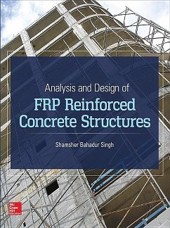
Shamsher Bahadur Singh
Analysis and Design of Frp Reinforced Concrete Structures
Shamsher Bahadur Singh
Analysis and Design of Frp Reinforced Concrete Structures
- Gebundenes Buch
- Merkliste
- Auf die Merkliste
- Bewerten Bewerten
- Teilen
- Produkt teilen
- Produkterinnerung
- Produkterinnerung
This comprehensive reference provides proven design procedures for the use of fiber-reinforced polymer (FRP) materials for reinforcement, prestressing, and strengthening of reinforced concrete structures.
Andere Kunden interessierten sich auch für
![Steel-Reinforced Concrete Structures Steel-Reinforced Concrete Structures]() Mohamed Abdallah El-ReedySteel-Reinforced Concrete Structures105,99 €
Mohamed Abdallah El-ReedySteel-Reinforced Concrete Structures105,99 €![Durability of Reinforced Concrete Structures Durability of Reinforced Concrete Structures]() Paul ChessDurability of Reinforced Concrete Structures25,99 €
Paul ChessDurability of Reinforced Concrete Structures25,99 €![Strengthening of Concrete Structures Using Fiber Reinforced Polymers (FRP) Strengthening of Concrete Structures Using Fiber Reinforced Polymers (FRP)]() Hwai-Chung WuStrengthening of Concrete Structures Using Fiber Reinforced Polymers (FRP)161,99 €
Hwai-Chung WuStrengthening of Concrete Structures Using Fiber Reinforced Polymers (FRP)161,99 €![Rehabilitation of Metallic Civil Infrastructure Using Fiber Reinforced Polymer (Frp) Composites Rehabilitation of Metallic Civil Infrastructure Using Fiber Reinforced Polymer (Frp) Composites]() Rehabilitation of Metallic Civil Infrastructure Using Fiber Reinforced Polymer (Frp) Composites162,99 €
Rehabilitation of Metallic Civil Infrastructure Using Fiber Reinforced Polymer (Frp) Composites162,99 €![Principles of Reinforced Concrete Design Principles of Reinforced Concrete Design]() Mete A. SozenPrinciples of Reinforced Concrete Design191,99 €
Mete A. SozenPrinciples of Reinforced Concrete Design191,99 €![Design Guide for Concrete-filled Double Skin Steel Tubular Structures Design Guide for Concrete-filled Double Skin Steel Tubular Structures]() Lin-Hai Han (China Tsinghua University)Design Guide for Concrete-filled Double Skin Steel Tubular Structures20,99 €
Lin-Hai Han (China Tsinghua University)Design Guide for Concrete-filled Double Skin Steel Tubular Structures20,99 €![Design Guide for Concrete-filled Double Skin Steel Tubular Structures Design Guide for Concrete-filled Double Skin Steel Tubular Structures]() Lin-Hai HanDesign Guide for Concrete-filled Double Skin Steel Tubular Structures25,99 €
Lin-Hai HanDesign Guide for Concrete-filled Double Skin Steel Tubular Structures25,99 €-
-
-
This comprehensive reference provides proven design procedures for the use of fiber-reinforced polymer (FRP) materials for reinforcement, prestressing, and strengthening of reinforced concrete structures.
Produktdetails
- Produktdetails
- Verlag: McGraw-Hill Education - Europe
- ed
- Seitenzahl: 352
- Erscheinungstermin: 28. Januar 2015
- Englisch
- Abmessung: 239mm x 208mm x 18mm
- Gewicht: 796g
- ISBN-13: 9780071847896
- ISBN-10: 0071847898
- Artikelnr.: 41885090
- Herstellerkennzeichnung
- Libri GmbH
- Europaallee 1
- 36244 Bad Hersfeld
- gpsr@libri.de
Professor Shamsher Bahadur Singh has 25 years of teaching and research experience and postdoctoral fellowship in USA. His area of specialization is in structural engineering with composite structure as major area. Furthermore, he has effectively contributed to all kinds academic and research work such as review of CURIE Journal, PS projects, examiners for BITASAT for higher degree admission, participation in Ph.D qualifying institute. He is also the reviewer of many prestigious journals such as ASCE Journal of Composites for Construction, International Journal of Earth Science and Engineer, ACI Structural Journal, IJE, and Journal of Korean Society of Civil Engineering. He has been member of various institute committees such construction committee, committee for recruitment of project engineer, and recruitment of BITS faculty at IIT Delhi. He is also the editorial board member of IJEE Journal, Journal of Civil Engineering and Architecture, published by Lublin University of Technology, Faculty of Civil Engineering and Architecture.
Chapter 1. Introduction
1.1. Evolution of FRP Reinforcement
1.2. Review of FRP Composites
1.3. The Importance of the Polymer Matrix
1.3.1. Matrix polymers
1.3.2. Polyester resins
1.3.3. Structural considerations in processing polymer matrix resins
1.3.4. Reinforcing fibers for structural composites
1.3.5. Effects of fiber length on laminate properties
1.3.6. Bonding interphase
1.3.7. Design considerations
1.4. Description of Fibers
1.4.1. Forms of glass fiber reinforcements
1.4.2. Behavior of glass fibers under load
1.4.3. Carbon fibers
1.4.4. Aramid fibers
1.4.5. Other organic fibers
1.4.6. Hybrid reinforcements
1.5. Manufacturing and Processing of Composites
1.5.1. Steps of fabrication scheme
1.5.2. Manufacturing methods
1.6. Sandwich Construction
1.7. Compression Molding
1.8. Multi-Axial Fabric for Structural Components
1.9. Fabrication of Stirrups
1.10. FRP Composites
1.11. FRP Composite Applications
1.12. Composite Mechanics
1.12.1. Laminate terminology
1.12.2. Composite product forms
1.13. Laminates Types and Stacking Sequence
Chapter 2. Material Characteristics of FRP Bars
2.1. Physical and Mechanical Properties
2.2. Physical Properties
2.3. Mechanical Properties and Behavior
2.3.1. Tensile behavior
2.3.2. Compressive behavior
2.3.3. Shear behavior
2.3.4. Bond behavior
2.4. Time-Dependent Behavior
2.4.1. Creep rupture
2.4.2. Fatigue
2.5. Durability
2.6. Recommended Materials and Construction Practices
2.6.1. Strength and modulus grades of FRP bars
2.6.2. Surface geometry, bar sizes, and bar identification
2.7. Construction Practices
2.7.1. Handling and storage of materials
2.7.2. Placement and assembly of materials
2.8. Quality Control and Inspection
Chapter 3. History and Uses of FRP Technology
3.1. FRP Composites in Japan
3.1.1. Development of FRP materials
3.1.2. Development of design methods in Japan
3.1.3. Typical FRP reinforced concrete structures in Japan
3.1.4. FRP for retrofitting and repair
3.1.5. Future uses of FRP
3.1.6. FRP construction activities in Europe
3.2. Reinforced and Prestressed Concrete: Some Applications
3.2.1. Rehabilitation and strengthening
3.2.2. Design guidelines
3.3. FRP Prestressing in the USA
3.3.1. Historical development of FRP tendons
3.3.2. Research and demonstration projects
3.3.3. Future prospects
Chapter 4. Design of RC Structures Reinforced with FRP Bars
4.1. Design Philosophy
4.1.1. Design material properties
4.1.2. Flexural design philosophy
4.1.3. Nominal flexural capacity
4.1.4. Strength reduction factor for flexure (¿)
4.1.5. Check for minimum
4.1.6. Serviceability
4.2. Shear
4.2.1. Shear design philosophy
4.2.2. Shear failure modes
4.2.3. Minimum shear reinforcement
4.2.4. Shear failure due to crushing of the web
4.2.5. Detailing of shear stirrups
4.2.6. Punching shear strength of FRP reinforced, two-way concrete slab
4.3. ISIS Canada Design Approach for Flexure
4.3.1. Flexural strength
4.3.2. Serviceability
4.4. Design Approach for CFRP Prestressed Concrete Bridge Beams
4.4.1. Theoretical development of design equations
4.4.2 Deflection and stesses under service load condition
4.4.3. Nonlinear response
E4.1. Design Example 1
E4.2. Design Example 2
E4.3. Design Example 3
E4.4. Design Example 4: A Case Study Problem
E4.5. Design Example 5: Case Study of CFRP Prestressed Concrete Double-T
Beam
E4.6. Design Example 6: Case Study of Cfrp Prestressed Concrete Box-Beam
E4.7. Design Example
Chapter 5. Design Philosophy for FRP External Strengthening Systems
5.1. Introduction
5.1.1. Non-prestressed soffit plates
5.1.2. End anchorage for unstressed (non-prestressed) plates
5.1.3. Prestressed soffit

