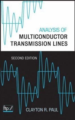
Clayton R. Paul
Analysis of Multiconductor Transmission Lines
Clayton R. Paul
Analysis of Multiconductor Transmission Lines
- Gebundenes Buch
- Merkliste
- Auf die Merkliste
- Bewerten Bewerten
- Teilen
- Produkt teilen
- Produkterinnerung
- Produkterinnerung
The essential textbook for electrical engineering students and professionals now in a valuable new edition The increasing use of high speed digital technology requires that all electrical engineers have a working knowledge of transmission lines. However, because of the introduction of computer engineering courses into already crowded four year undergraduate programs, the transmission line courses in many electrical engineering programs have been relegated to a senior technical elective, if offered at all. Now, Analysis of Multiconductor Transmission Lines, Second Edition has been significantly…mehr
Andere Kunden interessierten sich auch für
- J. A. Brandao FariaElectromagnetic Foundations of Electrical Engineering155,99 €
- Clayton R. PaulTransmission Lines in Digital Systems for EMC Practitioners117,99 €
- Junwei LuHarmonic Balance Finite Element Method167,99 €
- Clayton R. PaulTransmission Lines in Digital and Analog Electronic Systems146,99 €
- Enrique E. AchaVsc-Facts-Hvdc152,99 €
- Adrian IoinoviciPower Electronics and Energy Conversion Systems, Volume 1185,99 €
- Bo ZhangChaos Analysis and Chaotic EMI Suppression of DC-DC Converters160,99 €
-
-
-
The essential textbook for electrical engineering students and professionals now in a valuable new edition The increasing use of high speed digital technology requires that all electrical engineers have a working knowledge of transmission lines. However, because of the introduction of computer engineering courses into already crowded four year undergraduate programs, the transmission line courses in many electrical engineering programs have been relegated to a senior technical elective, if offered at all. Now, Analysis of Multiconductor Transmission Lines, Second Edition has been significantly updated and reorganized to fill the need for a structured course on transmission lines in a senior undergraduate or graduate level electrical engineering program. In this new edition, each broad analysis topic, e.g., per unit length parameters, frequency domain analysis, time domain analysis, and incident field excitation, now has a chapter concerning two conductor lines followed immediately by a chapter on MTLs for that topic. This enables instructors to emphasize two conductor lines or MTLs or both. In addition to the reorganization of the material, this Second Edition now contains important advancements in analysis methods that have developed since the previous edition, such as methods for achieving signal integrity (SI) in high speed digital interconnects, the finite difference, time domain (FDTD) solution methods, and the time domain to frequency domain transformation (TDFD) method. Furthermore, the content of Chapters 8 and 9 on digital signal propagation and signal integrity application has been considerably expanded upon to reflect all of the vital information current and future designers of high speed digital systems need to know. Complete with an accompanying FTP site, appendices with descriptions of numerous FORTRAN computer codes that implement all the techniques in the text, and a brief but thorough tutorial on the SPICE/PSPICE circuit analysis program, Analysis of Multiconductor Transmission Lines, Second Edition is an indispensable textbook for students and a valuable resource for industry professionals.
Hinweis: Dieser Artikel kann nur an eine deutsche Lieferadresse ausgeliefert werden.
Produktdetails
- Produktdetails
- Verlag: Wiley & Sons
- 2. Aufl.
- Seitenzahl: 816
- Erscheinungstermin: 1. Januar 2008
- Englisch
- Abmessung: 236mm x 163mm x 41mm
- Gewicht: 1245g
- ISBN-13: 9780470131541
- ISBN-10: 0470131543
- Artikelnr.: 22846168
- Herstellerkennzeichnung
- Libri GmbH
- Europaallee 1
- 36244 Bad Hersfeld
- 06621 890
Clayton R. Paul, PhD, is Professor and the Sam Nunn Eminent Professor of Aerospace Systems Engineering in the Department of Electrical Engineering and Computer Engineering at Mercer University in Macon, Georgia. He is also Emeritus Professor of Electrical Engineering at the University of Kentucky. Dr. Paul is the author of numerous textbooks on EE subjects and technical papers, the majority of which are in his primary research area of EMC of electronic systems. He is a Fellow of the IEEE and an Honorary Life Member of the IEEE EMC Society.
Preface xvii 1 Introduction 1 1.1 Examples of Multiconductor Transmission-Line Structures 5 1.2 Properties of the TEM Mode of Propagation 8 1.3 The Transmission-Line Equations: A Preview 18 1.3.1 Unique Definition of Voltage and Current for the TEM Mode of Propagation 19 1.3.2 Defining the Per-Unit-Length Parameters 22 1.3.3 Obtaining the Transmission-Line Equations from the Transverse Electromagnetic Field Equations 28 1.3.4 Properties of the Per-Unit-Length Parameters 30 1.4 Classification of Transmission Lines 32 1.4.1 Uniform versus Nonuniform Lines 33 1.4.2 Homogeneous versus Inhomogeneous Surrounding Media 35 1.4.3 Lossless versus Lossy Lines 36 1.5 Restrictions on the Applicability of the Transmission-Line Equation Formulation 37 1.5.1 Higher Order Modes 38 1.5.1.1 The Infinite, Parallel-Plate Transmission Line 38 1.5.1.2 The Coaxial Transmission Line 43 1.5.1.3 Two-Wire Lines 44 1.5.2 Transmission-Line Currents versus Antenna Currents 45 1.6 The Time Domain versus the Frequency Domain 47 1.6.1 The Fourier Series and Transform 50 1.6.2 Spectra and Bandwidth of Digital Waveforms 52 1.6.3 Computing the Time-Domain Response of Transmission Lines Having Linear Terminations Using Fourier Methods and Superposition 56 Problems 61 References 69 2 The Transmission-Line Equations for Two-Conductor Lines 71 2.1 Derivation of the Transmission-Line Equations from the Integral Form of Maxwell's Equations 71 2.2 Derivation of the Transmission-Line Equations from the Per-Unit-Length Equivalent Circuit 77 2.3 Properties of the Per-Unit-Length Parameters 78 2.4 Incorporating Frequency-Dependent Losses 79 2.4.1 Properties of the Frequency-Domain Per-Unit-Length Impedance
(
) and Admittance
(
) 81 Problems 85 References 88 3 The Transmission-Line Equations for Multiconductor Lines 89 3.1 Derivation of the Multiconductor Transmission-Line Equations from the Integral Form of Maxwell's Equations 89 3.2 Derivation of the Multiconductor Transmission-Line Equations from the Per-Unit-Length Equivalent Circuit 99 3.3 Summary of the MTL Equations 101 3.4 Incorporating Frequency-Dependent Losses 102 3.5 Properties of the Per-Unit-Length Parameter Matrices L, C, G 103 Problems 108 References 109 4 The Per-Unit-Length Parameters for Two-Conductor Lines 110 4.1 Definitions of the Per-Unit-Length Parameters l, c,and g 111 4.2 Lines Having Conductors of Circular, Cylindrical Cross Section (Wires) 113 4.2.1 Fundamental Subproblems for Wires 113 4.2.1.1 The Method of Images 118 4.2.2 Per-Unit-Length Inductance and Capacitance for Wire-Type Lines 119 4.2.3 Per-Unit-Length Conductance and Resistance for Wire-Type Lines 130 4.3 Lines Having Conductors of Rectangular Cross Section (PCB Lands) 144 4.3.1 Per-Unit-Length Inductance and Capacitance for PCB-Type Lines 145 4.3.2 Per-Unit-Length Conductance and Resistance for PCB-Type Lines 148 Problems 156 References 158 5 The Per-Unit-Length Parameters for Multiconductor Lines 160 5.1 Definitions of the Per-Unit-Length Parameter Matrices L, C, and G 161 5.1.1 The Generalized capacitance Matrix c 167 5.2 Multiconductor Lines Having Conductors of Circular, Cylindrical Cross Section (Wires) 171 5.2.1 Wide-Separation Approximations for Wires in Homogeneous Media 171 5.2.1.1 n + 1 Wires 173 5.2.1.2 n Wires Above an Infinite, Perfectly Conducting Plane 173 5.2.1.3 n Wires Within a Perfectly Conducting Cylindrical Shield 174 5.2.2 Numerical Methods for the General Case 176 5.2.2.1 Applications to Inhomogeneous Dielectric Media 181 5.2.3 Computed Results: Ribbon Cables 187 5.3 Multiconductor Lines Having Conductors of Rectangular Cross Section 189 5.3.1 Method of Moments (MoM) Techniques 190 5.3.1.1 Applications to Printed Circuit Boards 199 5.3.1.2 Applications to Coupled Microstrip Lines 211 5.3.1.3 Applications to Coupled Striplines 219 5.4 Finite Difference Techniques 223 5.5 Finite-Element Techniques 229 Problems 237 References 239 6 Frequency-Domain Analysis of Two-Conductor Lines 240 6.1 The Transmission-Line Equations in the Frequency Domain 241 6.2 The General Solution for Lossless Lines 242 6.2.1 The Reflection Coefficient and Input Impedance 244 6.2.2 Solutions for the Terminal Voltages and Currents 247 6.2.3 The SPICE (PSPICE) Solution for Lossless Lines 250 6.2.4 Voltage and Current as a Function of Position on the Line 252 6.2.5 Matching and VSWR 255 6.2.6 Power Flow on a Lossless Line 256 6.3 The General Solution for Lossy Lines 258 6.3.1 The Low-Loss Approximation 260 6.4 Lumped-Circuit Approximate Models of the Line 265 6.5 Alternative Two-Port Representations of the Line 269 6.5.1 The Chain Parameters 270 6.5.2 Approximating Abruptly Nonuniform Lines with the Chain-Parameter Matrix 273 6.5.3 The Z and Y Parameters 275 Problems 278 7 Frequency-Domain Analysis of Multiconductor Lines 282 7.1 The MTL Transmission-Line Equations in the Frequency Domain 282 7.2 The General Solution for An (n + 1)-Conductor Line 284 7.2.1 Decoupling the MTL Equations by Similarity Transformations 284 7.2.2 Solution for Line Categories 291 7.2.2.1 Perfect Conductors in Lossy, Homogeneous Media 292 7.2.2.2 Lossy Conductors in Lossy, Homogeneous Media 293 7.2.2.3 Perfect Conductors in Lossless, Inhomogeneous Media 296 7.2.2.4 The General Case: Lossy Conductors in Lossy, Inhomogeneous Media 298 7.2.2.5 Cyclic-Symmetric Structures 298 7.3 Incorporating the Terminal Conditions 305 7.3.1 The Generalized Thevenin Equivalent 305 7.3.2 The Generalized Norton Equivalent 308 7.3.3 Mixed Representations 310 7.4 Lumped-Circuit Approximate Characterizations 312 7.5 Alternative 2n-Port Characterizations 314 7.5.1 Analogy of the Frequency-Domain MTL Equations to State-Variable Equations 314 7.5.2 Characterizing the Line as a 2n-Port with the Chain-Parameter Matrix 316 7.5.3 Properties of the Chain-Parameter Matrix 318 7.5.4 Approximating Nonuniform Lines with the Chain-Parameter Matrix 322 7.5.5 The Impedance and Admittance Parameter Matrix Characterizations 323 7.6 Power Flow and the Reflection Coefficient Matrix 327 7.7 Computed and Experimental Results 332 7.7.1 Ribbon Cables 332 7.7.2 Printed Circuit Boards 335 Problems 338 References 342 8 Time-Domain Analysis of Two-Conductor Lines 343 8.1 The Solution for Lossless Lines 344 8.1.1 Wave Tracing and the Reflection Coefficients 346 8.1.2 Series Solutions and the Difference Operator 356 8.1.3 The Method of Characteristics and a Two-Port Model of the Line 361 8.1.4 The SPICE (PSPICE) Solution for Lossless Lines 365 8.1.5 The Laplace Transform Solution 368 8.1.5.1 Lines with Capacitive and Inductive Loads 370 8.1.6 Lumped-Circuit Approximate Models of the Line 373 8.1.6.1 When is the Line Electrically Short in the Time Domain? 374 8.1.7 The Time-Domain to Frequency-Domain (TDFD) Transformation Method 375 8.1.8 The Finite-Difference, Time-Domain (FDTD) Method 379 8.1.8.1 The Magic Time Step 385 8.1.9 Matching for Signal Integrity 392 8.1.9.1 When is Matching Required? 398 8.1.9.2 Effects of Line Discontinuities 399 8.2 Incorporation of Losses 406 8.2.1 Representing Frequency-Dependent Losses 408 8.2.1.1 Representing Losses in the Medium 408 8.2.1.2 Representing Losses in the Conductors and Skin Effect 410 8.2.1.3 Convolution with Frequency-Dependent Losses 415 8.2.2 The Time-Domain to Frequency-Domain (TDFD) Transformation Method 421 8.2.3 The Finite-Difference, Time-Domain (FDTD) Method 423 8.2.3.1 Including Frequency-Independent Losses 423 8.2.3.2 Including Frequency-Dependent Losses 427 8.2.3.3 Prony's Method for Representing a Function 431 8.2.3.4 Recursive Convolution 434 8.2.3.5 An Example: A High-Loss Line 439 8.2.3.6 A Correction for the FDTD Errors 443 8.2.4 Lumped-Circuit Approximate Characterizations 447 8.2.5 The Use of Macromodels in Modeling the Line 450 8.2.6 Representing Frequency-Dependent Functions in the Time Domain Using Pade Methods 453 Problems 461 References 467 9 Time-Domain Analysis of Multiconductor Lines 470 9.1 The Solution for Lossless Lines 470 9.1.1 The Recursive Solution for MTLs 471 9.1.2 Decoupling the MTL Equations 476 9.1.2.1 Lossless Lines in Homogeneous Media 478 9.1.2.2 Lossless Lines in Inhomogeneous Media 479 9.1.2.3 Incorporating the Terminal Conditions via the SPICE Program 482 9.1.3 Lumped-Circuit Approximate Characterizations 487 9.1.4 The Time-Domain to Frequency-Domain (TDFD) Transformation Method 488 9.1.5 The Finite-Difference, Time-Domain (FDTD) Method 488 9.1.5.1 Including Dynamic and/or Nonlinear Terminations in the FDTD Analysis 490 9.2 Incorporation of Losses 496 9.2.1 The Time-Domain to Frequency-Domain (TDFD) Method 498 9.2.2 Lumped-Circuit Approximate Characterizations 498 9.2.3 The Finite-Difference, Time-Domain (FDTD) Method 499 9.2.4 Representation of the Lossy MTL with the Generalized Method of Characteristics 501 9.2.5 Model Order Reduction (MOR) Methods 512 9.2.5.1 Pade Approximation of the Matrix Exponential 512 9.2.5.2 Asymptotic Waveform Evaluation (AWE) 515 9.2.5.3 Complex Frequency Hopping (CFH) 518 9.2.5.4 Vector Fitting 518 9.3 Computed and Experimental Results 524 9.3.1 Ribbon Cables 526 9.3.2 Printed Circuit Boards 530 Problems 537 References 541 10 Literal (Symbolic) Solutions for Three-Conductor Lines 544 10.1 The Literal Frequency-Domain Solution for a Homogeneous Medium 548 10.1.1 Inductive and Capacitive Coupling 554 10.1.2 Common-Impedance Coupling 556 10.2 The Literal Time-Domain Solution for a Homogeneous Medium 558 10.2.1 Explicit Solution 560 10.2.2 Weakly Coupled Lines 562 10.2.3 Inductive and Capacitive Coupling 564 10.2.4 Common-Impedance Coupling 567 10.3 Computed and Experimental Results 567 10.3.1 A Three-Wire Ribbon Cable 568 10.3.2 A Three-Conductor Printed Circuit Board 569 Problems 575 References 576 11 Incident Field Excitation of Two-Conductor Lines 578 11.1 Derivation of the Transmission-Line Equations for Incident Field Excitation 578 11.1.1 Equivalence of Source Representations 585 11.2 The Frequency-Domain Solution 586 11.2.1 Solution of the Transmission-Line Equations 586 11.2.2 Simplified Forms of the Excitations 592 11.2.3 Incorporating the Line Terminations 594 11.2.4 Uniform Plane-Wave Excitation of the Line 598 11.2.4.1 Special Cases 602 11.2.4.2 One Conductor Above a Ground Plane 606 11.2.5 Comparison with Predictions of Method of Moments Codes 610 11.3 The Time-Domain Solution 611 11.3.1 The Laplace Transform Solution 611 11.3.2 Uniform Plane-Wave Excitation of the Line 620 11.3.3 A SPICE Equivalent Circuit 625 11.3.4 The Time-Domain to Frequency-Domain (TDFD) Transformation 628 11.3.5 The Finite-Difference, Time-Domain (FDTD) Solution Method 628 11.3.6 Computed Results 635 Problems 638 References 639 12 Incident Field Excitation of Multiconductor Lines 641 12.1 Derivation of the MTL Equations for Incident Field Excitation 642 12.1.1 Equivalence of Source Representations 648 12.2 Frequency-Domain Solutions 650 12.2.1 Solution of the MTL Equations 651 12.2.2 Simplified Forms of the Excitations 653 12.2.3 Incorporating the Line Terminations 655 12.2.3.1 Lossless Lines in Homogeneous Media 658 12.2.4 Lumped-Circuit Approximate Characterizations 660 12.2.5 Uniform Plane-Wave Excitation of the Line 660 12.3 The Time-Domain Solution 667 12.3.1 Decoupling the MTL Equations 668 12.3.2 A SPICE Equivalent Circuit 674 12.3.3 Lumped-Circuit Approximate Characterizations 681 12.3.4 The Time-Domain to Frequency-Domain (TDFD) Transformation 681 12.3.5 The Finite-Difference, Time-Domain (FDTD) Solution Method 682 12.4 Computed Results 686 Problems 691 References 692 13 Transmission-Line Networks 693 13.1 Representation of Lossless Lines with the SPICE Model 696 13.2 Representation with Lumped-Circuit Approximate Models 699 13.3 Representation via the Admittance or Impedance 2n-Port Parameters 699 13.4 Representation with the BLT Equations 712 13.5 Direct Time-Domain Solutions in Terms of Traveling Waves 721 13.6 A Summary of Methods for Analyzing Multiconductor Transmission Lines 726 Problems 727 References 728 Publications by the Author Concerning Transmission Lines 729 Appendix A. Description of Computer Software 736 A.1 Programs for the Calculation of the Per-Unit-Length Parameters 738 A.1.1 Wide-Separation Approximations for Wires: WIDESEP.FOR 738 A.1.2 Ribbon Cables: RIBBON.FOR 740 A.1.3 Printed Circuit Boards: PCB.FOR 743 A.1.4 Coupled Microstrip Structures: MSTRP.FOR 745 A.1.5 Coupled Stripline Structures: STRPLINE.FOR 746 A.2 Frequency-Domain Analysis 747 A.2.1 General: MTL.FOR 747 A.3 Time-Domain Analysis 748 A.3.1 Time-Domain to Frequency-Domain Transformation: TIMEFREQ.FOR 748 A.3.2 Branin's Method Extended to Multiconductor Lines: BRANIN.FOR 748 A.3.3 Finite Difference-Time Domain Method: FINDIF.FOR 749 A.3.4 Finite-Difference-Time-Domain Method: FDTDLOSS.FOR 749 A.4 SPICE/PSPICE Subcircuit Generation Programs 749 A.4.1 General Solution, Lossless Lines: SPICEMTL.FOR 750 A.4.2 Lumped-Pi Circuit, Lossless Lines: SPICELPI.FOR 750 A.4.3 Inductive-Capacitive Coupling Model: SPICELC.FOR 751 A.5 Incident Field Excitation 752 A.5.1 Frequency-Domain Program: INCIDENT.FOR 752 A.5.2 SPICE/PSPICE Subcircuit Model: SPICEINC.FOR 753 A.5.3 Finite-Difference, Time-Domain (FDTD) Model: FDTDINC.FOR 754 References 755 Appendix B. A SPICE (PSPICE) Tutorial 756 B.1 Creating the SPICE or PSPICE Program 757 B.2 Circuit Description 758 B.3 Execution Statements 763 B.4 Output Statements 765 B.5 Examples 767 B.6 The Subcircuit Model 769 References 771 Index 773
(
) and Admittance
(
) 81 Problems 85 References 88 3 The Transmission-Line Equations for Multiconductor Lines 89 3.1 Derivation of the Multiconductor Transmission-Line Equations from the Integral Form of Maxwell's Equations 89 3.2 Derivation of the Multiconductor Transmission-Line Equations from the Per-Unit-Length Equivalent Circuit 99 3.3 Summary of the MTL Equations 101 3.4 Incorporating Frequency-Dependent Losses 102 3.5 Properties of the Per-Unit-Length Parameter Matrices L, C, G 103 Problems 108 References 109 4 The Per-Unit-Length Parameters for Two-Conductor Lines 110 4.1 Definitions of the Per-Unit-Length Parameters l, c,and g 111 4.2 Lines Having Conductors of Circular, Cylindrical Cross Section (Wires) 113 4.2.1 Fundamental Subproblems for Wires 113 4.2.1.1 The Method of Images 118 4.2.2 Per-Unit-Length Inductance and Capacitance for Wire-Type Lines 119 4.2.3 Per-Unit-Length Conductance and Resistance for Wire-Type Lines 130 4.3 Lines Having Conductors of Rectangular Cross Section (PCB Lands) 144 4.3.1 Per-Unit-Length Inductance and Capacitance for PCB-Type Lines 145 4.3.2 Per-Unit-Length Conductance and Resistance for PCB-Type Lines 148 Problems 156 References 158 5 The Per-Unit-Length Parameters for Multiconductor Lines 160 5.1 Definitions of the Per-Unit-Length Parameter Matrices L, C, and G 161 5.1.1 The Generalized capacitance Matrix c 167 5.2 Multiconductor Lines Having Conductors of Circular, Cylindrical Cross Section (Wires) 171 5.2.1 Wide-Separation Approximations for Wires in Homogeneous Media 171 5.2.1.1 n + 1 Wires 173 5.2.1.2 n Wires Above an Infinite, Perfectly Conducting Plane 173 5.2.1.3 n Wires Within a Perfectly Conducting Cylindrical Shield 174 5.2.2 Numerical Methods for the General Case 176 5.2.2.1 Applications to Inhomogeneous Dielectric Media 181 5.2.3 Computed Results: Ribbon Cables 187 5.3 Multiconductor Lines Having Conductors of Rectangular Cross Section 189 5.3.1 Method of Moments (MoM) Techniques 190 5.3.1.1 Applications to Printed Circuit Boards 199 5.3.1.2 Applications to Coupled Microstrip Lines 211 5.3.1.3 Applications to Coupled Striplines 219 5.4 Finite Difference Techniques 223 5.5 Finite-Element Techniques 229 Problems 237 References 239 6 Frequency-Domain Analysis of Two-Conductor Lines 240 6.1 The Transmission-Line Equations in the Frequency Domain 241 6.2 The General Solution for Lossless Lines 242 6.2.1 The Reflection Coefficient and Input Impedance 244 6.2.2 Solutions for the Terminal Voltages and Currents 247 6.2.3 The SPICE (PSPICE) Solution for Lossless Lines 250 6.2.4 Voltage and Current as a Function of Position on the Line 252 6.2.5 Matching and VSWR 255 6.2.6 Power Flow on a Lossless Line 256 6.3 The General Solution for Lossy Lines 258 6.3.1 The Low-Loss Approximation 260 6.4 Lumped-Circuit Approximate Models of the Line 265 6.5 Alternative Two-Port Representations of the Line 269 6.5.1 The Chain Parameters 270 6.5.2 Approximating Abruptly Nonuniform Lines with the Chain-Parameter Matrix 273 6.5.3 The Z and Y Parameters 275 Problems 278 7 Frequency-Domain Analysis of Multiconductor Lines 282 7.1 The MTL Transmission-Line Equations in the Frequency Domain 282 7.2 The General Solution for An (n + 1)-Conductor Line 284 7.2.1 Decoupling the MTL Equations by Similarity Transformations 284 7.2.2 Solution for Line Categories 291 7.2.2.1 Perfect Conductors in Lossy, Homogeneous Media 292 7.2.2.2 Lossy Conductors in Lossy, Homogeneous Media 293 7.2.2.3 Perfect Conductors in Lossless, Inhomogeneous Media 296 7.2.2.4 The General Case: Lossy Conductors in Lossy, Inhomogeneous Media 298 7.2.2.5 Cyclic-Symmetric Structures 298 7.3 Incorporating the Terminal Conditions 305 7.3.1 The Generalized Thevenin Equivalent 305 7.3.2 The Generalized Norton Equivalent 308 7.3.3 Mixed Representations 310 7.4 Lumped-Circuit Approximate Characterizations 312 7.5 Alternative 2n-Port Characterizations 314 7.5.1 Analogy of the Frequency-Domain MTL Equations to State-Variable Equations 314 7.5.2 Characterizing the Line as a 2n-Port with the Chain-Parameter Matrix 316 7.5.3 Properties of the Chain-Parameter Matrix 318 7.5.4 Approximating Nonuniform Lines with the Chain-Parameter Matrix 322 7.5.5 The Impedance and Admittance Parameter Matrix Characterizations 323 7.6 Power Flow and the Reflection Coefficient Matrix 327 7.7 Computed and Experimental Results 332 7.7.1 Ribbon Cables 332 7.7.2 Printed Circuit Boards 335 Problems 338 References 342 8 Time-Domain Analysis of Two-Conductor Lines 343 8.1 The Solution for Lossless Lines 344 8.1.1 Wave Tracing and the Reflection Coefficients 346 8.1.2 Series Solutions and the Difference Operator 356 8.1.3 The Method of Characteristics and a Two-Port Model of the Line 361 8.1.4 The SPICE (PSPICE) Solution for Lossless Lines 365 8.1.5 The Laplace Transform Solution 368 8.1.5.1 Lines with Capacitive and Inductive Loads 370 8.1.6 Lumped-Circuit Approximate Models of the Line 373 8.1.6.1 When is the Line Electrically Short in the Time Domain? 374 8.1.7 The Time-Domain to Frequency-Domain (TDFD) Transformation Method 375 8.1.8 The Finite-Difference, Time-Domain (FDTD) Method 379 8.1.8.1 The Magic Time Step 385 8.1.9 Matching for Signal Integrity 392 8.1.9.1 When is Matching Required? 398 8.1.9.2 Effects of Line Discontinuities 399 8.2 Incorporation of Losses 406 8.2.1 Representing Frequency-Dependent Losses 408 8.2.1.1 Representing Losses in the Medium 408 8.2.1.2 Representing Losses in the Conductors and Skin Effect 410 8.2.1.3 Convolution with Frequency-Dependent Losses 415 8.2.2 The Time-Domain to Frequency-Domain (TDFD) Transformation Method 421 8.2.3 The Finite-Difference, Time-Domain (FDTD) Method 423 8.2.3.1 Including Frequency-Independent Losses 423 8.2.3.2 Including Frequency-Dependent Losses 427 8.2.3.3 Prony's Method for Representing a Function 431 8.2.3.4 Recursive Convolution 434 8.2.3.5 An Example: A High-Loss Line 439 8.2.3.6 A Correction for the FDTD Errors 443 8.2.4 Lumped-Circuit Approximate Characterizations 447 8.2.5 The Use of Macromodels in Modeling the Line 450 8.2.6 Representing Frequency-Dependent Functions in the Time Domain Using Pade Methods 453 Problems 461 References 467 9 Time-Domain Analysis of Multiconductor Lines 470 9.1 The Solution for Lossless Lines 470 9.1.1 The Recursive Solution for MTLs 471 9.1.2 Decoupling the MTL Equations 476 9.1.2.1 Lossless Lines in Homogeneous Media 478 9.1.2.2 Lossless Lines in Inhomogeneous Media 479 9.1.2.3 Incorporating the Terminal Conditions via the SPICE Program 482 9.1.3 Lumped-Circuit Approximate Characterizations 487 9.1.4 The Time-Domain to Frequency-Domain (TDFD) Transformation Method 488 9.1.5 The Finite-Difference, Time-Domain (FDTD) Method 488 9.1.5.1 Including Dynamic and/or Nonlinear Terminations in the FDTD Analysis 490 9.2 Incorporation of Losses 496 9.2.1 The Time-Domain to Frequency-Domain (TDFD) Method 498 9.2.2 Lumped-Circuit Approximate Characterizations 498 9.2.3 The Finite-Difference, Time-Domain (FDTD) Method 499 9.2.4 Representation of the Lossy MTL with the Generalized Method of Characteristics 501 9.2.5 Model Order Reduction (MOR) Methods 512 9.2.5.1 Pade Approximation of the Matrix Exponential 512 9.2.5.2 Asymptotic Waveform Evaluation (AWE) 515 9.2.5.3 Complex Frequency Hopping (CFH) 518 9.2.5.4 Vector Fitting 518 9.3 Computed and Experimental Results 524 9.3.1 Ribbon Cables 526 9.3.2 Printed Circuit Boards 530 Problems 537 References 541 10 Literal (Symbolic) Solutions for Three-Conductor Lines 544 10.1 The Literal Frequency-Domain Solution for a Homogeneous Medium 548 10.1.1 Inductive and Capacitive Coupling 554 10.1.2 Common-Impedance Coupling 556 10.2 The Literal Time-Domain Solution for a Homogeneous Medium 558 10.2.1 Explicit Solution 560 10.2.2 Weakly Coupled Lines 562 10.2.3 Inductive and Capacitive Coupling 564 10.2.4 Common-Impedance Coupling 567 10.3 Computed and Experimental Results 567 10.3.1 A Three-Wire Ribbon Cable 568 10.3.2 A Three-Conductor Printed Circuit Board 569 Problems 575 References 576 11 Incident Field Excitation of Two-Conductor Lines 578 11.1 Derivation of the Transmission-Line Equations for Incident Field Excitation 578 11.1.1 Equivalence of Source Representations 585 11.2 The Frequency-Domain Solution 586 11.2.1 Solution of the Transmission-Line Equations 586 11.2.2 Simplified Forms of the Excitations 592 11.2.3 Incorporating the Line Terminations 594 11.2.4 Uniform Plane-Wave Excitation of the Line 598 11.2.4.1 Special Cases 602 11.2.4.2 One Conductor Above a Ground Plane 606 11.2.5 Comparison with Predictions of Method of Moments Codes 610 11.3 The Time-Domain Solution 611 11.3.1 The Laplace Transform Solution 611 11.3.2 Uniform Plane-Wave Excitation of the Line 620 11.3.3 A SPICE Equivalent Circuit 625 11.3.4 The Time-Domain to Frequency-Domain (TDFD) Transformation 628 11.3.5 The Finite-Difference, Time-Domain (FDTD) Solution Method 628 11.3.6 Computed Results 635 Problems 638 References 639 12 Incident Field Excitation of Multiconductor Lines 641 12.1 Derivation of the MTL Equations for Incident Field Excitation 642 12.1.1 Equivalence of Source Representations 648 12.2 Frequency-Domain Solutions 650 12.2.1 Solution of the MTL Equations 651 12.2.2 Simplified Forms of the Excitations 653 12.2.3 Incorporating the Line Terminations 655 12.2.3.1 Lossless Lines in Homogeneous Media 658 12.2.4 Lumped-Circuit Approximate Characterizations 660 12.2.5 Uniform Plane-Wave Excitation of the Line 660 12.3 The Time-Domain Solution 667 12.3.1 Decoupling the MTL Equations 668 12.3.2 A SPICE Equivalent Circuit 674 12.3.3 Lumped-Circuit Approximate Characterizations 681 12.3.4 The Time-Domain to Frequency-Domain (TDFD) Transformation 681 12.3.5 The Finite-Difference, Time-Domain (FDTD) Solution Method 682 12.4 Computed Results 686 Problems 691 References 692 13 Transmission-Line Networks 693 13.1 Representation of Lossless Lines with the SPICE Model 696 13.2 Representation with Lumped-Circuit Approximate Models 699 13.3 Representation via the Admittance or Impedance 2n-Port Parameters 699 13.4 Representation with the BLT Equations 712 13.5 Direct Time-Domain Solutions in Terms of Traveling Waves 721 13.6 A Summary of Methods for Analyzing Multiconductor Transmission Lines 726 Problems 727 References 728 Publications by the Author Concerning Transmission Lines 729 Appendix A. Description of Computer Software 736 A.1 Programs for the Calculation of the Per-Unit-Length Parameters 738 A.1.1 Wide-Separation Approximations for Wires: WIDESEP.FOR 738 A.1.2 Ribbon Cables: RIBBON.FOR 740 A.1.3 Printed Circuit Boards: PCB.FOR 743 A.1.4 Coupled Microstrip Structures: MSTRP.FOR 745 A.1.5 Coupled Stripline Structures: STRPLINE.FOR 746 A.2 Frequency-Domain Analysis 747 A.2.1 General: MTL.FOR 747 A.3 Time-Domain Analysis 748 A.3.1 Time-Domain to Frequency-Domain Transformation: TIMEFREQ.FOR 748 A.3.2 Branin's Method Extended to Multiconductor Lines: BRANIN.FOR 748 A.3.3 Finite Difference-Time Domain Method: FINDIF.FOR 749 A.3.4 Finite-Difference-Time-Domain Method: FDTDLOSS.FOR 749 A.4 SPICE/PSPICE Subcircuit Generation Programs 749 A.4.1 General Solution, Lossless Lines: SPICEMTL.FOR 750 A.4.2 Lumped-Pi Circuit, Lossless Lines: SPICELPI.FOR 750 A.4.3 Inductive-Capacitive Coupling Model: SPICELC.FOR 751 A.5 Incident Field Excitation 752 A.5.1 Frequency-Domain Program: INCIDENT.FOR 752 A.5.2 SPICE/PSPICE Subcircuit Model: SPICEINC.FOR 753 A.5.3 Finite-Difference, Time-Domain (FDTD) Model: FDTDINC.FOR 754 References 755 Appendix B. A SPICE (PSPICE) Tutorial 756 B.1 Creating the SPICE or PSPICE Program 757 B.2 Circuit Description 758 B.3 Execution Statements 763 B.4 Output Statements 765 B.5 Examples 767 B.6 The Subcircuit Model 769 References 771 Index 773