R. F. Egerton
Electron Energy-Loss Spectroscopy in the Electron Microscope
R. F. Egerton
Electron Energy-Loss Spectroscopy in the Electron Microscope
- Gebundenes Buch
- Merkliste
- Auf die Merkliste
- Bewerten Bewerten
- Teilen
- Produkt teilen
- Produkterinnerung
- Produkterinnerung
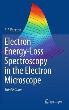
Within the last 30 years, electron energy-loss spectroscopy (EELS) has become a standard analytical technique used in the transmission electron microscope to extract chemical and structural information down to the atomic level. In two previous editions, Electron Energy-Loss Spectroscopy in the Electron Microscope has become the standard reference guide to the instrumentation, physics and procedures involved, and the kind of results obtainable. Within the last few years, the commercial availability of lens-aberration correctors and electron-beam monochromators has further increased the spatial…mehr
Andere Kunden interessierten sich auch für
![New Horizons of Applied Scanning Electron Microscopy New Horizons of Applied Scanning Electron Microscopy]() Kenichi ShimizuNew Horizons of Applied Scanning Electron Microscopy81,99 €
Kenichi ShimizuNew Horizons of Applied Scanning Electron Microscopy81,99 €![Planewaves, Pseudopotentials, and the LAPW Method Planewaves, Pseudopotentials, and the LAPW Method]() David J. SinghPlanewaves, Pseudopotentials, and the LAPW Method75,99 €
David J. SinghPlanewaves, Pseudopotentials, and the LAPW Method75,99 €![New Horizons of Applied Scanning Electron Microscopy New Horizons of Applied Scanning Electron Microscopy]() Kenichi ShimizuNew Horizons of Applied Scanning Electron Microscopy77,99 €
Kenichi ShimizuNew Horizons of Applied Scanning Electron Microscopy77,99 €![Advanced Transmission Electron Microscopy Advanced Transmission Electron Microscopy]() Jian Min ZuoAdvanced Transmission Electron Microscopy71,99 €
Jian Min ZuoAdvanced Transmission Electron Microscopy71,99 €![X-Ray Diffraction Crystallography X-Ray Diffraction Crystallography]() Yoshio WasedaX-Ray Diffraction Crystallography164,99 €
Yoshio WasedaX-Ray Diffraction Crystallography164,99 €![Single Semiconductor Quantum Dots Single Semiconductor Quantum Dots]() Single Semiconductor Quantum Dots149,99 €
Single Semiconductor Quantum Dots149,99 €![Applied Scanning Probe Methods XIII Applied Scanning Probe Methods XIII]() Applied Scanning Probe Methods XIII112,99 €
Applied Scanning Probe Methods XIII112,99 €-
-
-
Within the last 30 years, electron energy-loss spectroscopy (EELS) has become a standard analytical technique used in the transmission electron microscope to extract chemical and structural information down to the atomic level. In two previous editions, Electron Energy-Loss Spectroscopy in the Electron Microscope has become the standard reference guide to the instrumentation, physics and procedures involved, and the kind of results obtainable. Within the last few years, the commercial availability of lens-aberration correctors and electron-beam monochromators has further increased the spatial and energy resolution of EELS. This thoroughly updated and revised Third Edition incorporates these new developments, as well as advances in electron-scattering theory, spectral and image processing, and recent applications in fields such as nanotechnology. The appendices now contain a listing of inelastic mean free paths and a description of more than 20 MATLAB programs for calculating EELS data.
Hinweis: Dieser Artikel kann nur an eine deutsche Lieferadresse ausgeliefert werden.
Hinweis: Dieser Artikel kann nur an eine deutsche Lieferadresse ausgeliefert werden.
Produktdetails
- Produktdetails
- Verlag: Springer US
- Artikelnr. des Verlages: 12721894
- 3rd edition 2011
- Seitenzahl: 504
- Erscheinungstermin: 29. Juli 2011
- Englisch
- Abmessung: 241mm x 160mm x 30mm
- Gewicht: 916g
- ISBN-13: 9781441995827
- ISBN-10: 144199582X
- Artikelnr.: 32768553
- Herstellerkennzeichnung Die Herstellerinformationen sind derzeit nicht verfügbar.
Chapter 1. An Introduction to EELS
1.1. Interaction of Fast Electrons with a Solid
1.2. The Electron Energy-Loss Spectrum
1.3. The Development of Experimental Techniques
1.3.1. Energy-Selecting (Energy-Filtering) Electron Microscopes
1.3.2. Spectrometers as Attachments to Electron Microscopes
1.4. Alternative Analytical Methods
1.4.1. Ion-Beam Methods
1.4.2. Incident Photons
1.4.3. Electron-Beam Techniques
1.5. Comparison of EELS and EDX Spectroscopy
1.5.1. Detection Limits and Spatial Resolution
1.5.2. Specimen Requirements
1.5.3. Accuracy of Quantification
1.5.4. Ease of Use and Information Content
1.6. Further Reading
Chapter 2. Energy-Loss Instrumentation
2.1. Energy-Analyzing and Energy-Selecting Systems
2.1.1. The Magnetic-Prism Spectrometer
2.1.2. Energy-Filtering Magnetic-Prism Systems
2.1.3. The Wien Filter
2.1.4. Electron Monochromators
2.2. Optics of a Magnetic-Prism Spectrometer
2.2.1. First-Order Properties
2.2.2. Higher-Order Focusing
2.2.3. Spectrometer Sesigns
2.2.4. Practical Considerations
2.2.5. Spectrometer Alignment
2.3. The Use of Prespectrometer Lenses
2.3.1. TEM Imaging and Diffraction Modes
2.3.2. Effect of Lens Aberrations on Spatial Resolution
2.3.3. Effect of Lens Aberrations on Collection Efficiency
2.3.4. Effect of TEM Lenses on Energy Resolution
2.3.5. STEM Optics
>2.4.1.Spectrum Shift and Scanning
2.4.2. Spectrometer Background
2.4.3. Coincidence Counting
2.4.4. Serial Recording of the Energy-Loss Spectrum
2.4.5. DQE of a Single-Channel System
2.4.6. Serial-Mode Signal Processing
2.5. Parallel Recording of Energy-Loss Data
2.5.1. Types of Self-Scanning Diode Array
2.5.2. Indirect Exposure Systems
2.5.3. Direct Exposure Systems
2.5.4. DQE of a Parallel-Recording System
2.5.5. Dealing with Diode Array Artifacts
2.6. Energy-Selected Imaging (ESI)
2.6.1. Post-Column Energy Filter
2.6.2. In-Column Filters
2.6.3. Energy Filtering in STEM Mode
2.6.4. Spectrum-Imaging
2.6.5. Elemental Mapping
2.6.6. Comparison of Energy-Filtered TEM and STEM
2.6.7. Z-Contrast and Z-Ratio Imaging
Chapter 3. Physics of Electron Scattering
3.1. Elastic Scattering
3.1.1. General Formulas
3.1.2. Atomic Models
3.1.3. Diffraction Effects
3.1.4. Electron Channeling
3.1.5. Phonon Scattering
3.1.6. Energy Transfer in Elastic Scattering
3.2. Inelastic Scattering
3.2.1. Atomic Models
3.2.2. Bethe Theory
3.2.3. Dielectric Formulation
3.2.4. Solid-State Effects
3.3. Excitation of Outer-Shell Electrons
3.3.1. Volume Plasmons
3.3.2. Single-Electron Excitation
3.3.3. Excitons
3.3.4. Radiation Losses
3.3.5. Surface Plasmons
3.3.6. Surface-Reflection Spectra
3.3.7. Plasmon Modes in Small Particles
3.4. Single, Plural, and Multiple Scattering
3.4.1. Poisson's Law
3.4.2. Angular Distribution of Plural Inelastic Scattering
3.4.3. Influence of Elastic Scattering
3.4.4. Multiple Scattering
3.4.5. Coherent Double-Plasmon Excitation
3.5. The Spectral Background to Inner-Shell Edges
3.5.1. Valence-Electron Scattering
3.5.2. Tails of Core-Loss Edges
3.5.3. Bremsstrahlung Energy Losses
3.5.4. Plural Scattering Contributions to the Background
3.6. Atomic Theory of Inner-Shell Excitation
3.6.1. Generalized Oscillator Strength
3.6.2. Relativistic Kinematics of Scattering
3.6.3. Ionization Cross Sections
3.7. The Form of Inner-Shell Edges
3.7.1. Basic Edge Shapes
3.7.2. Dipole Selection Rule
3.7.3. Effect of Plural Scattering
3.7.4. Chemical Shifts in Threshold Energy
3.8. Near-Edge Fine Structure (ELNES)
3.8.1. Densities-of-States Interpretation
3.8.2. Multiple-Scattering Interpretation
3.8.3. Molecular-Orbital Theory
3.8.4. Multiplet and Crystal-Field Effects ¿
3.9. Extended Energy-Loss Fine Structure (EXELFS)
3.10. Core Excitation in Anisotropic Materials
3.11. Delocalization of inelastic Scattering
Chapter 4. Quantitative Analysis of Energy-Loss Data
4.1. Deconvolution of Low-Loss Spectra
4.1.1. Fourier-Log Method
4.1.2. Fourier-Ratio Method
4.1.3. Bayesian Deconvolution
4.1.4. Other Methods
>4.3.Deconvolution of Core-Loss Data
4.3.1. Fourier-Log Method
4.3.2. Fourier-Ratio Method
4.3.3. Bayesian Deconvolution
4.3.4. Other Methods
4.4. Separation of Spectral Components
4.4.1. Least-Squares Fitting
4.4.2. Two-Area Fitting
4.4.3. Background-Fitting Errors
4.4.4. Multiple Least-Squares Fitting
4.4.5. Multivariate Statistical Analysis
4.4.6. Energy- and Spatial-Difference Techniques
4.5. Elemental Quantification
4.5.1. Integration Method
4.5.2. Calculation of Partial Cross Sections
4.5.3. Correction for Incident-Beam Convergence
4.5.4. Quantification from MLS Fitting
4.6. Analysis of Extended Energy-Loss Fine Structure
4.6.1. Fourier-Transform Method
4.6.2. Curve-Fitting Procedure
4.7. Simulation of Energy-Loss Near-Edge Structure (ELNES)
4.7.1. Multiple-Scattering Calculations
4.7.2. Band-Structure Calculations
Chapter 5. TEM Applications of EELS
5.1. Measurement of Specimen Thickness
5.1.1. Log-Ratio Method
5.1.2. Absolute Thickness from the K-K Sum Rule
5.1.3. Mass-Thickness from the Bethe Sum Rule
5.2. Low-Loss Spectroscopy
5.2.1. Identification from Low-Loss Fine Structure
5.2.2. Measurement of Plasmon Energy and Alloy Composition
5.2.3. Characterization of Small Particles
5.3. Energy-Filtered Images and Diffraction Patterns
5.3.1. Zero-Loss Images
5.3.2. Zero-Loss Diffraction Patterns
5.3.3. Low-Loss Images
5.3.4. Z-Ratio Images
5.3.5.Contrast Tuning and MPL Imaging
5.3.6. Core-Loss Images and Elemental Mapping
5.4. Elemental Analysis from Core-Loss Spectroscopy
5.4.1. Measurement of Hydrogen and Helium
5.4.2. Measurement of Lithium, Beryllium, and Boron
5.4.3. Measurement of Carbon, Nitrogen, and Oxygen
5.4.4. Measurement of Fluorine and Heavier Elements
5.5. Spatial Resolution and Detection Limits
5.5.1. Electron-Optical Considerations
5.5.2. Loss of Resolution due to Elastic Scattering
5.5.3. Delocalization of Inelastic Scattering
5.5.4. Statistical Limitations and Radiation Damage
5.6. Structural Information from EELS
5.6.1. Orientation Dependence of Ionization Edges
5.6.2. Core-Loss Diffraction Patterns
5.6.3. ELNES Fingerprinting
5.6.4. Valency and Magnetic Measurements from White-Line Ratios
5.6.5. Use of Chemical Shifts
5.6.6. Use of Extended Fine Structure
5.6.7. Electron-Compton (ECOSS) Measurements
5.7. Application to Specific Materials
5.7.1. Semiconductors and Electronic Devices
5.7.2. Ceramics and High-Temperature Superconductors
5.7.3. Carbon-Based Materials
5.7.4. Polymers and Biological Specimens
5.7.5. Radiation Damage and Hole Drilling
Appendix A. Bethe Theory forHigh Incident Energies and Anisotropic
Materials
Appendix B. Computer Programs
B.1. First-Order Spectrometer Focusing
>B.3. Lenz-Model Elastic and Inelastic CrossSections
B.4. Simulation of a Plural-Scattering Distribution
B.5. Fourier-Log Deconvolution
B.6. Maximum-Likelihood Deconvolution
B.7. Drude Simulation of a Low-Loss Spectrum
B.8. Kramers-Kronig Analysis
B.9. Kröger Simulation of a Low-Loss Spectrum
B.10. Core-Loss Simulation
B.11. Fourier-Ratio Deconvolution
B.12. Incident-Convergence Correction
B.13. Hydrogenic K-shell Cross Sections
B.14. Modified-Hydrogenic L-shell Cross Sections
B.15. Parameterized K-, L-, N-, N- and O-shell Cross Sections B.16.
Measurement of Absolute Specimen Thickness
B.17. Total-Inelastic and Plasmon Mean Free Paths
B.18. Constrained Power-Law Background Fitting
Appendix C. Plasmon Energies and Inelastic Mean Free Paths
Appendix D. Inner-Shell Energies and Edge Shapes
Appendix E. Electron Wavelengths and Relativistic Factors; Physical
Constants
Appendix F. Options for Energy-Loss Data Acquisition
References
Indexetc.

