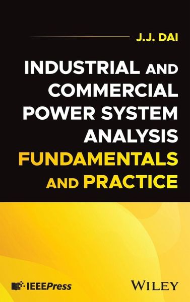
J. J. Dai
Industrial and Commercial Power System Analysis Fundamentals and Practice
J. J. Dai
Industrial and Commercial Power System Analysis Fundamentals and Practice
- Gebundenes Buch
- Merkliste
- Auf die Merkliste
- Bewerten Bewerten
- Teilen
- Produkt teilen
- Produkterinnerung
- Produkterinnerung
Understand industrial and commercial power systems with this essential guide Power system analysis is an essential component of new system design, system expansion, and existing system operation. A wide range of published standards and computing tools is available for the analysis of industrial and commercial power systems. This is the first book to provide specific information and practical analysis. Industrial and Commercial Power System Analysis: Fundamentals and Practice fills this gap with a handy, accessible reference for students and practicing engineers. Its chapters cover basic…mehr
Andere Kunden interessierten sich auch für
- Takalani Bridget ThovhakaleBenefits of Retrofitting Commercial Buildings38,99 €
- Mohamed BregawModeling, Simulation and Optimization of Residential/Commercial Energy42,99 €
- Ian M. ShapiroEnergy Audits and Improvements for Commercial Buildings113,99 €
- Fouad A. S. SolimanSolar-Wind Hybrid Renewable Energy for Sustainable Agriculture36,99 €
- Yi JiangDecarbonize Public and Commercial Buildings81,99 €
- Improving Energy Efficiency in Commercial Buildings and Smart Communities125,99 €
-
-
-
Understand industrial and commercial power systems with this essential guide Power system analysis is an essential component of new system design, system expansion, and existing system operation. A wide range of published standards and computing tools is available for the analysis of industrial and commercial power systems. This is the first book to provide specific information and practical analysis. Industrial and Commercial Power System Analysis: Fundamentals and Practice fills this gap with a handy, accessible reference for students and practicing engineers. Its chapters cover basic equipment and system configurations and their associated computer models, operating conditions, numerical solution essentials, and analysis objectives and approaches. The result is a volume which directly contributes to the skills needed to apply power systems analysis software in research and industrial applications. Readers will also find: * An introductory chapter outlining the basic characteristics of industrial and commercial power systems * Detailed discussion of topics including modeling and simulation techniques, data requirements and data preparation, tuning and validation, study scenario selections, and many more * Applicable industrial codes and standards * Concrete examples of industrial and commercial power system analysis in practice Industrial and Commercial Power System Analysis: Fundamentals and Practice is ideal for undergraduates, graduates, or practicing engineers looking for an up-to-date reference on the essential tools and standards of power system analysis.
Hinweis: Dieser Artikel kann nur an eine deutsche Lieferadresse ausgeliefert werden.
Produktdetails
- Produktdetails
- Verlag: John Wiley & Sons Inc
- Seitenzahl: 304
- Erscheinungstermin: 31. Dezember 2024
- Englisch
- ISBN-13: 9781394265039
- ISBN-10: 1394265034
- Artikelnr.: 71706660
- Herstellerkennzeichnung
- Libri GmbH
- Europaallee 1
- 36244 Bad Hersfeld
- gpsr@libri.de
- Verlag: John Wiley & Sons Inc
- Seitenzahl: 304
- Erscheinungstermin: 31. Dezember 2024
- Englisch
- ISBN-13: 9781394265039
- ISBN-10: 1394265034
- Artikelnr.: 71706660
- Herstellerkennzeichnung
- Libri GmbH
- Europaallee 1
- 36244 Bad Hersfeld
- gpsr@libri.de
JJ Dai, PhD, is a retired physical scientist and electrical engineer. He has authored and co-authored more than 30 technical papers in the field of power system modeling and analysis. He is a resgitered Professional Engineer in the state of California, USA, a Member of IEEE, and a past Chairman of the Power System Analysis Subcommittee of the IEEE Industrial Applications Society (IAS). He has been actively involved in the development of IEEE standards on I&C power system analysis.
About the Author xiii
Preface and Acknowledgments xv
1 Industrial and Commercial (I&C) Power System 1
1.1 General Background 1
1.2 I&C Power System Single-Line Presentation 2
1.3 Components and Equipment in I&C Power Systems 2
1.3.1 Power Supply and Generation 2
1.3.2 Power Distribution 4
1.3.3 Loads 8
1.3.4 Power Conditioning 9
1.3.5 Auxiliary System 13
References 15
2 I&C Power System Analysis Applications 17
2.1 Objectives and Procedures 17
2.2 Type of Analysis 18
2.2.1 Conceptual Design 18
2.2.1.1 Design Focus 18
2.2.1.2 Criteria 19
2.2.1.3 Tasks 19
2.2.1.4 Procedures 19
2.2.2 Preliminary Design 21
2.2.2.1 Objective 21
2.2.2.2 Focus and Procedures 22
2.2.3 Detailed Design 25
2.2.3.1 Objectives 25
2.2.3.2 Procedures and Analysis Types 26
2.2.4 Multiphase Analysis 42
2.2.4.1 System Analysis Phases 42
2.2.4.2 Database Evolution 42
2.2.4.3 Iterations for System Analysis 44
2.2.5 New System 44
2.2.5.1 Types of System Analysis 44
2.2.5.2 Data Considerations 45
2.2.5.3 Operation Requirements and Guidelines 45
2.2.6 Existing System 45
2.2.6.1 Needs for Existing System Analysis 45
2.2.6.2 Some Examples for Existing System Analysis 46
2.2.6.3 Types of Existing System Analysis 47
2.2.6.4 Data Considerations 47
2.2.6.5 Model Validation 47
2.2.6.6 Operation Requirements and Guidelines 48
2.2.7 System Expansion 48
2.2.7.1 Types of System Analysis 48
2.2.7.2 Data Considerations 49
2.2.7.3 Operation Requirements and Guidelines 49
2.2.7.4 Issues Related to the Existing System 49
2.3 Scenarios 51
2.3.1 Planning Based 51
2.3.1.1 Load Flow Analysis 51
2.3.1.2 Short-Circuit and Fault Analysis 52
2.3.1.3 Motor Starting Analysis 52
2.3.2 Normal Operation Based 53
2.3.2.1 Load Flow Analysis 53
2.3.2.2 Short-Circuit and Fault Analysis 53
2.3.2.3 Protection and Device Coordination 53
2.3.2.4 Motor Starting Analysis 54
2.3.2.5 Harmonic Analysis 56
2.3.2.6 Transient Stability Analysis 56
2.3.3 Contingency Based 60
2.3.3.1 Load Flow Analysis 60
2.3.3.2 Transient Stability Analysis 61
2.3.4 Optimization Based 61
2.3.4.1 Optimal Power Flow Analysis 61
2.3.4.2 Short-Circuit and Protection Coordination Analysis 65
2.3.5 An Analysis Example 65
2.3.5.1 System Description 66
2.3.5.2 Operation Modes and Constraints 66
2.3.5.3 Studies Scenario Selections 68
2.4 Data and Results 76
2.4.1 Input Data 76
2.4.2 Study Data 106
2.4.3 Output Data 106
References 109
3 Computer Modeling of I&C Power Systems 111
3.1 Equipment and Component Modeling 111
3.1.1 Utility 112
3.1.2 Synchronous Machine 114
3.1.3 Induction Machine 121
3.1.4 Line and Cable 124
3.1.5 Transformer 125
3.1.6 Generic Load 127
3.1.7 Motor Load 128
3.1.8 Capacitor and Static Var Compensator (SVC) 129
3.1.9 Short Line Reactor and Choker 130
3.1.10 Harmonic Filter 131
3.1.11 Harmonic Source 131
3.1.12 Power Converter 134
3.1.13 Protective Device 136
3.2 Control System Model 140
3.2.1 Generator Control 141
3.2.2 Motor Starting Control 147
3.2.3 Adjustable Speed Control 152
3.2.4 Transformer Control 153
3.2.5 Capacitor and SVC Control 154
3.3 Network Modeling 155
3.3.1 Admittance Equation and Y-Bus 156
3.3.2 Impedance Equation and Z-Bus 157
3.3.3 Constant Power Components 158
3.3.4 Constant Voltage Components 159
3.3.5 Current Injection Components 161
3.4 Model Integration 161
3.5 Operation Modeling 163
3.5.1 Utility Connected System 163
3.5.2 Island System 164
References 165
4 Industrial and Commercial Power System Mathematical Solutions 167
4.1 Load Flow Solution 167
4.1.1 Direct Iteration Solution 168
4.1.2 First-Order Solution 170
4.1.3 Higher-Order Solution 171
4.2 Short-Circuit Solution 172
4.2.1 Balanced Fault Solution 172
4.2.2 Unbalanced Fault Solution 176
4.3 Motor Starting Solution 179
4.3.1 Static Solution 179
4.3.2 Dynamic Solution 181
4.4 Harmonic Solution 183
4.4.1 Harmonic Load Flow Solution 184
4.4.2 Harmonic Frequency Scan Solution 186
4.5 Transient Stability Solution 188
4.5.1 Initialization and Steady-State Solution 188
4.5.1.1 Data Preparation 188
4.5.1.2 Initialization 189
4.5.1.3 Steady-State Stability 189
4.5.2 Dynamic Solution 191
4.5.2.1 Main Iteration and Solution Process 191
4.5.2.2 Event Simulation 194
References 194
5 Numerical Simulation Techniques 195
5.1 Linear Algebraic Equation 195
5.1.1 Direct Solution Method 197
5.1.1.1 Gaussian Elimination 197
5.1.1.2 LU (Lower-Upper) Decomposition 198
5.1.2 Iterative Solution Method 199
5.1.2.1 Gauss-Seidel Method 199
5.1.2.2 Newton-Raphson Method 200
5.2 Differential Equation 201
5.2.1.1 Euler's Method 201
5.2.1.2 Prediction-Correction Method 202
5.3 Integral Equation 203
5.3.1.1 Simpson's Method 204
5.3.1.2 Differential Equation Method 204
5.4 Mixed Linear Algebraic and Differential Equation 205
References 206
6 Examples of Practical I&C Power System Analysis 207
6.1 Objectives 207
6.2 Voltage Drops Study 208
6.2.1 Introduction 208
6.2.1.1 Causes of Voltage Drops 208
6.2.1.2 Types of Voltage Drops 209
6.2.1.3 Voltage Drop Limitations 209
6.2.1.4 Remedy for Voltage Drops 210
6.2.2 A Voltage Drops Analysis Case 211
6.2.2.1 System Description 211
6.2.2.2 Initial Simulation Results 211
6.2.2.3 Remedy Action 213
6.3 Power Factor Study 216
6.3.1 Introduction 216
6.3.1.1 Causes of Low-Power Factor 216
6.3.1.2 Power Factor Correction Methods 216
6.3.1.3 Special Notes on Power Factor Correction 216
6.3.2 A Power Factor Correction Analysis Case 217
6.3.2.1 System Description and Initial Simulation 217
6.3.2.2 Remedy Action 218
6.3.2.3 Validation 219
6.4 Over-Current Study 220
6.4.1 Introduction 220
6.4.2 An Over-Current Analysis Case 221
6.4.2.1 System Description and Fault Currents 221
6.4.2.2 Over-Current Breaker Sizing 221
6.5 Reactive Power Inrush Study 224
6.5.1 Introduction 224
6.5.2 A Reactive Power Inrush Analysis Case 225
6.5.2.1 System Description 225
6.5.2.2 Comparison of Starting Methods 225
6.6 Harmonic Distortion Study 229
6.6.1 Introduction 229
6.6.1.1 Harmonic Distortion Limits 229
6.6.1.2 Mitigation of Harmonic Distortions 230
6.6.2 A Harmonic Distortion Analysis Case 231
6.6.2.1 System Description 231
6.6.2.2 Initial Study Results 231
6.6.2.3 Mitigation Actions 233
6.6.2.4 Mitigation Validation 233
6.7 Rotor Angle Swing Study 235
6.7.1 Introduction 235
6.7.1.1 Causes of Rotor Angle Swings 235
6.7.1.2 Rotor Angle Swing Plots and Limits 236
6.7.1.3 Rotor Angle Swing Control 236
6.7.2 A Rotor Angle Swing Analysis Case 237
6.7.2.1 System Description 237
6.7.2.2 Dynamic Components Model 237
6.7.2.3 Initial Condition 240
6.7.2.4 Transient Stability Study Parameters 240
6.7.2.5 Disturbances 241
6.7.2.6 Variable Monitoring and Alert 241
6.7.2.7 Simulation and the First Remedy Action 241
6.7.2.8 The Second Remedy Action and Validation 243
6.8 Frequency Decay Study 246
6.8.1 Introduction 246
6.8.1.1 Rationale of Frequency Balance 246
6.8.1.2 Effect of Spinning Reserve 246
6.8.2 A Frequency Decay and Protection Case 247
6.8.2.1 System Description 247
6.8.2.2 Study Scenario and Simulation Results 248
6.8.2.3 Load Shedding Remedy Development 248
6.8.2.4 Load Shedding Simulation Validation 251
References 253
Appendix A Relevant IEEE Standards and References 255
A.1 IEEE Std. 3002.2 255
A.1.1 Scope of the Standard 256
A.1.2 Load-Flow Analysis Objectives 256
A.1.3 Load-Flow Analysis Methodologies 257
A.2 IEEE Std. 3002.3 258
A.2.1 Scope of the Standard 258
A.2.2 Short-Circuit Analysis Objectives 259
A.2.3 Short-Circuit Analysis Methodologies 259
A.3 IEEE Std. 3002.7 260
A.3.1 Scope of the Standard 261
A.3.2 Motor-Starting Analysis Objectives 261
A.3.3 Motor-Starting Analysis Methodologies 262
A.4 IEEE Std. 3002.8 262
A.4.1 Scope of the Standard 263
A.4.2 Harmonic Analysis Objectives 263
A.4.3 Harmonic Analysis Methodologies 265
A.5 IEEE Standard on Transient Stability Analysis 265
A.5.1 Scope of the Paper 266
A.5.2 Transient Stability Analysis Objectives 266
A.5.3 Transient Stability Analysis Methodologies 267
References 268
Index 269