- Gebundenes Buch
- Merkliste
- Auf die Merkliste
- Bewerten Bewerten
- Teilen
- Produkt teilen
- Produkterinnerung
- Produkterinnerung
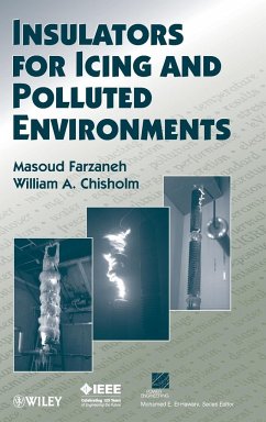
With the widespread use of EHV equipment in winter environments, winter flashovers at air temperature close to melting point have become a critical design constraint. This book explores the issues of electrical insulators for icing and polluted environments, enabling engineers and environmental specialists to carry out appropriate measurements, understand how they change with time and weather, and work out how they compare with the upper limits set by insulator dimensions. It is essential reading for anyone involved with issues relating to icing and pollution problems in electrical line insulation.…mehr
Andere Kunden interessierten sich auch für
![Electric Distribution Systems Electric Distribution Systems]() SallamElectric Distribution Systems133,99 €
SallamElectric Distribution Systems133,99 €![Power Quality Power Quality]() Bhim SinghPower Quality151,99 €
Bhim SinghPower Quality151,99 €![Importance Measures in Reliability, Risk, and Optimization Importance Measures in Reliability, Risk, and Optimization]() Way KuoImportance Measures in Reliability, Risk, and Optimization128,99 €
Way KuoImportance Measures in Reliability, Risk, and Optimization128,99 €![Operation and Control of Electric Energy Processing Systems Operation and Control of Electric Energy Processing Systems]() Operation and Control of Electric Energy Processing Systems105,99 €
Operation and Control of Electric Energy Processing Systems105,99 €![Power Distribution System Reliability Power Distribution System Reliability]() Ali ChowdhuryPower Distribution System Reliability173,99 €
Ali ChowdhuryPower Distribution System Reliability173,99 €![Reliability Technology Reliability Technology]() Norman PascoeReliability Technology113,99 €
Norman PascoeReliability Technology113,99 €![Real-Time Stability Assessment in Modern Power System Control Centers Real-Time Stability Assessment in Modern Power System Control Centers]() S C SavulescuReal-Time Stability Assessment in Modern Power System Control Centers159,99 €
S C SavulescuReal-Time Stability Assessment in Modern Power System Control Centers159,99 €-
-
-
With the widespread use of EHV equipment in winter environments, winter flashovers at air temperature close to melting point have become a critical design constraint. This book explores the issues of electrical insulators for icing and polluted environments, enabling engineers and environmental specialists to carry out appropriate measurements, understand how they change with time and weather, and work out how they compare with the upper limits set by insulator dimensions. It is essential reading for anyone involved with issues relating to icing and pollution problems in electrical line insulation.
Produktdetails
- Produktdetails
- Verlag: John Wiley & Sons / Wiley
- Seitenzahl: 706
- Erscheinungstermin: 1. Oktober 2009
- Englisch
- Abmessung: 240mm x 161mm x 42mm
- Gewicht: 1223g
- ISBN-13: 9780470282342
- ISBN-10: 0470282347
- Artikelnr.: 26487827
- Herstellerkennzeichnung
- Libri GmbH
- Europaallee 1
- 36244 Bad Hersfeld
- gpsr@libri.de
Masoud Farzaneh, PhD, is an internationally renowned expert in the field of power engineering. He is a Fellow of the IEEE, the IET, and the Engineering Institute of Canada. Prof. Farzaneh is currently Director of the International Center on Icing and Power Network Engineering (CenGivre), as well as Chairholder of the NSERC/Hydro-Quebec Industrial Chair on Atmospheric Icing of Power Network Equipment (CIGELE) and of the Canada Research Chair on Engineering of Power Network Atmospheric Icing (INGIVRE) at University of Québec in Chicoutimi (UQAC), Canada. He is Associate Editor of IEEE Transactions on Dielectrics and Electrical Insulation, Chair of IEEE DEIS Outdoor Insulation Committee, and Convenor of CIGRé WG B2.29 on de-icing and anti-icing of overhead lines. William A. Chisholm, PhD, is an IEEE Fellow and an internationally acknowledged expert in lightning protection, electrical insulation, and thermal rating of power systems. Dr. Chisholm is an Associate at Kinectrics in Toronto, Canada, and an Adjunct Professor at the University of Québec at Chicoutimi. He is Secretary of the PES Transmission and Distribution Committee.
PREFACE.
ACKNOWLEDGMENTS.
1. INTRODUCTION.
1.1. Scope and Objectives.
1.2. Power System Reliability.
1.3. The Insulation Coordination Process: What Is Involved?
1.4. Organization of the Book.
1.5. Précis.
2. INSULATORS FOR ELECTRIC POWER SYSTEMS.
2.1. Terminology for Insulators.
2.2. Classification of Insulators.
2.3. Insulator Construction.
2.4. Electrical Stresses on Insulators.
2.5. Environmental Stresses on Insulators.
2.6. Mechanical Stresses.
3. ENVIRONMENTAL EXPOSURE OF INSULATORS.
3.1. Pollution: What It Is.
3.2. Pollution Deposits on Power System Insulators.
3.3. Nonsoluble Electrically Inert Deposits.
3.4. Soluble Electrically Conductive Pollution.
3.5. Effects of Temperature on Electrical Conductivity.
3.6. Conversion to Equivalent Salt Deposit Density.
3.7. Self-Wetting of Contaminated Surfaces.
3.8. Surface Wetting by Fog Accretion.
3.9. Surface Wetting by Natural Precipitation.
3.10. Surface Wetting by Artificial Precipitation.
4. INSULATOR ELECTRICAL PERFORMANCE IN POLLUTION CONDITIONS.
4.1. Terminology for Electrical Performance in Pollution Conditions.
4.2. Air Gap Breakdown.
4.3. Breakdown of Polluted Insulators.
4.4. Outdoor Exposure Test Methods.
4.5. Indoor Test Methods for Pollution Flashovers.
4.6. Salt-Fog Test.
4.7. Clean-Fog Test Method.
4.8. Other Test Procedures.
4.9. Salt-Fog Test Results.
4.10. Clean-Fog Test Results.
4.11. Effects of Insulator Parameters.
4.12. Effects of Nonsoluble Deposit Density.
4.13. Pressure Effects on Contamination Tests.
4.14. Temperature Effects on Pollution Flashover.
5. CONTAMINATION FLASHOVER MODELS.
5.1. General Classifi cation of Partial Discharges.
5.2. Dry-Band Arcing on Contaminated Surfaces.
5.3. Electrical Arcing on Wet, Contaminated Surfaces.
5.4. Residual Resistance of Polluted Layer.
5.5. dc Pollution Flashover Modeling.
5.6. ac Pollution Flashover Modeling.
5.7. Theoretical Modeling for Cold-Fog Flashover.
5.8. Future Directions for Pollution Flashover Modeling.
6. MITIGATION OPTIONS FOR IMPROVED PERFORMANCE IN POLLUTION CONDITIONS.
6.1. Monitoring for Maintenance.
6.2. Cleaning of Insulators.
6.3. Coating of Insulators.
6.4. Adding Accessories.
6.5. Adding More Insulators.
6.6. Changing to Improved Designs.
6.7. Changing to Semiconducting Glaze.
6.8. Changing to Polymer Insulators.
7. ICING FLASHOVERS.
7.1. Terminology for Ice.
7.2. Ice Morphology.
7.3. Electrical Characteristics of Ice.
7.4. Ice Flashover Experience.
7.5. Ice Flashover Processes.
7.6. Icing Test Methods.
7.7. Ice Flashover Test Results.
7.8. Empirical Models for Icing Flashovers.
7.9. Mathematical Modeling of Flashover Process on Ice-Covered Insulators.
7.10. Environmental Corrections for Ice Surfaces.
7.11. Future Directions for Icing Flashover Modeling.
8. SNOW FLASHOVERS.
8.1. Terminology for Snow.
8.2. Snow Morphology.
8.3. Snow Electrical Characteristics.
8.4. Snow Flashover Experience.
8.5. Snow Flashover Process and Test Methods.
8.6. Snow Flashover Test Results.
8.7 Empirical Model for Snow Flashover.
8.8. Mathematical Modeling of Flashover Process on Snow-Covered Insulators.
8.9. Environmental Corrections for Snow Flashover.
8.10. Case Studies of Snow Flashover.
9. MITIGATION OPTIONS FOR IMPROVED PERFORMANCE IN ICE AND SNOW CONDITIONS.
9.1. Options for Mitigating Very Light and Light Icing.
9.2. Options for Mitigating Moderate Icing.
9.3. Options for Mitigating Heavy Icing.
9.4. Options for Mitigating Snow and Rime.
9.5. Alternatives for Mitigating Any Icing.
10. INSULATION COORDINATION FOR ICING AND POLLUTED ENVIRONMENTS.
10.1. The Insulation Coordination Process.
10.2. Deterministic and Probabilistic Methods.
10.3. IEEE 1313.2 Design Approach for Contamination.
10.4. IEC 60815 Design Approach for Contamination.
10.5. CIGRE Design Approach for Contamination.
10.6. Characteristics of Winter Pollution.
10.7. Winter Fog Events.
10.8. Freezing Rain and Freezing Drizzle Events.
10.9. Snow Climatology.
10.10. Deterministic Coordination for Leakage Distance.
10.11. Probabilistic Coordination for Leakage Distance.
10.12. Deterministic Coordination for Dry Arc Distance.
10.13. Probabilistic Coordination for Dry Arc Distance.
10.14. Case Studies.
APPENDIX A: MEASUREMENT OF INSULATOR CONTAMINATION LEVEL.
APPENDIX B: STANDARD CORRECTIONS FOR HUMIDITY, TEMPERATURE, AND PRESSURE.
APPENDIX C: TERMS RELATED TO ELECTRICAL IMPULSES.
INDEX.

