- Gebundenes Buch
- Merkliste
- Auf die Merkliste
- Bewerten Bewerten
- Teilen
- Produkt teilen
- Produkterinnerung
- Produkterinnerung
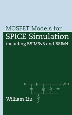
Beim integrierten Schaltkreisdesign spielt die Schaltkreissimulation eine wesentliche Rolle, wobei deren Genauigkeit von der Genauigkeit des verwendeten Transistormodells abhängig ist. BSIM3 (BSIM steht für Berkley Short-channel IGFET Model) wurde als erstes MOSFET Modell zur Standardisierung ausgewählt. Es wird erwartet, daß in den kommenden Jahren viele Halbleiterunternehmen zu BSIM3 wechseln. Dieses Buch erläutert die technischen Einzelheiten von BSIM 3, warum sich die meisten Unternehmen für dieses Modell entscheiden und wo es eingesetzt werden kann. Eines der fünf Kapitel widmet sich BSIM4, dem Nachfolgemodell von BSIM3.…mehr
Andere Kunden interessierten sich auch für
![Asynchronous Circuit Design Asynchronous Circuit Design]() Chris J. MyersAsynchronous Circuit Design180,99 €
Chris J. MyersAsynchronous Circuit Design180,99 €![Introduction to Microfabrication Introduction to Microfabrication]() Sami FranssilaIntroduction to Microfabrication94,99 €
Sami FranssilaIntroduction to Microfabrication94,99 €![VLSI Circuit Design Methodology VLSI Circuit Design Methodology]() Liming XiuVLSI Circuit Design Methodology105,99 €
Liming XiuVLSI Circuit Design Methodology105,99 €![Understanding Microelectronics Understanding Microelectronics]() Franco MalobertiUnderstanding Microelectronics75,99 €
Franco MalobertiUnderstanding Microelectronics75,99 €![Digital Circuit Boards Digital Circuit Boards]() Ralph MorrisonDigital Circuit Boards93,99 €
Ralph MorrisonDigital Circuit Boards93,99 €![Boolean Circuit Rewiring Boolean Circuit Rewiring]() Tak-Kei LamBoolean Circuit Rewiring144,99 €
Tak-Kei LamBoolean Circuit Rewiring144,99 €![Mobile 3D Graphics Soc Mobile 3D Graphics Soc]() Hoi-Jun YooMobile 3D Graphics Soc176,99 €
Hoi-Jun YooMobile 3D Graphics Soc176,99 €-
-
-
Beim integrierten Schaltkreisdesign spielt die Schaltkreissimulation eine wesentliche Rolle, wobei deren Genauigkeit von der Genauigkeit des verwendeten Transistormodells abhängig ist. BSIM3 (BSIM steht für Berkley Short-channel IGFET Model) wurde als erstes MOSFET Modell zur Standardisierung ausgewählt. Es wird erwartet, daß in den kommenden Jahren viele Halbleiterunternehmen zu BSIM3 wechseln.
Dieses Buch erläutert die technischen Einzelheiten von BSIM 3, warum sich die meisten Unternehmen für dieses Modell entscheiden und wo es eingesetzt werden kann. Eines der fünf Kapitel widmet sich BSIM4, dem Nachfolgemodell von BSIM3.
Dieses Buch erläutert die technischen Einzelheiten von BSIM 3, warum sich die meisten Unternehmen für dieses Modell entscheiden und wo es eingesetzt werden kann. Eines der fünf Kapitel widmet sich BSIM4, dem Nachfolgemodell von BSIM3.
Produktdetails
- Produktdetails
- Wiley - IEEE 1
- Verlag: Wiley & Sons
- 1. Auflage
- Seitenzahl: 600
- Erscheinungstermin: 21. Februar 2001
- Englisch
- Abmessung: 240mm x 161mm x 37mm
- Gewicht: 850g
- ISBN-13: 9780471396970
- ISBN-10: 0471396974
- Artikelnr.: 13801213
- Herstellerkennzeichnung
- Libri GmbH
- Europaallee 1
- 36244 Bad Hersfeld
- gpsr@libri.de
WILLIAM LIU, PhD, is a senior member of the technical staff at Texas Instruments, where he has worked since obtaining his PhD in electrical engineering from Stanford University in 1991. Dr. Liu has been TI's lead contact in mentoring the development of BSIM4 model equations with UC Berkeley, and has been in charge of the modeling development for LDMOS/DEMOS and RF-CMOS in TI's SPICE Modeling Laboratory. Dr. Liu has authored/coauthored five book chapters, and has written more than fifty journal papers on modeling, device characterization, and fabrication. Dr. Liu has also published two books on III-V device technologies. Dr. Liu holds sixteen U.S. patents and is a senior member of IEEE.
Preface.
1 Modeling Jargons.
1.1 SPICE Simulator and SPICE Model.
1.2 Numerical Iteration and Convergence.
1.3 Digital vs. Analog Models.
1.4 Smoothing Function and Single Equation.
1.5 Chain Rule.
1.6 Quasi-Static Approximation.
1.7 Terminal Charges and Charge Partition.
1.8 Charge Conservation.
1.9 Non-Quasi-Static and Quasi-Static y-Parameters.
1.10 Source-Referencing and Inverse Modeling.
1.11 Physical Model and Table-Lookup Model.
1.12 Scalable Model and Device Binning.
References and Notes.
2 Basic Facts About BSIM3.
2.1 What Is and What's Not Implemented in BSIM3.
2.2 DC Equivalent Circuit Model.
2.3 BSIM3's ^-Parameters.
2.4 Large-Signal Equivalent Circuit.
2.5 Small-Signal Model.
2.6 Noise Equivalent Circuit.
2.7 Special Operating Conditions: VDS .
References and Notes.
3 BSIM3 Parameters.
3.1 List of Parameters According to Function.
3.2 Alphabetical Glossary of BSIM3 Parameters.
3.3 Flow Diagram of SPICE Simulation.
References and Notes.
4 Improvable Areas of BSIM3.
4.1 Lack of Robust Non-Quasi-Static Models: Transient Analysis.
4.2 Problem with the 40/60 Partition: The "Killer NOR Gate".
4.3 Lack of Channel Resistance (NQS Effect; Small-Signal Analysis).
4.4 Incorrect Transconductance Dependency on Frequency.
4.5 Lack of Gate Resistance (and Associated Noise).
4.6 Lack of Substrate Distributed Resistance (and Associated Noise).
4.7 Incorrect Source/Drain Asymmetry at VDS = 0.
4.8 Incorrect Cgb Behaviors.
4.9 Capacitances with Wrong Signs.
4.10 Cgg Fit and Other Capacitance Issues.
4.11 Insufficient Noise Modeling (No Excess Short-Channel Thermal Noise).
4.12 Insufficient Noise Modeling (No Channel-Induced Gate Noise).
4.13 Incorrect Noise Figure Behavior.
4.14 Inconsistent Input-Referred Noise Behavior.
4.15 Possible Negative Transconductances.
4.16 Lack of GIDL (Gate-Induced Drain Leakage) Current.
4.17 Incorrect Subthreshold Behaviors.
4.18 Threshold Voltage Rollup.
4.19 Problems Associated with a Nonzero RDSW.
4.20 Other Nuisances.
References and Notes.
5. Improvements in BSIM4.
5.1 Introduction.
5.2 Physical and Electrical Oxide Thicknesses.
5.3 Strong Inversion Potential for Vertical Nonuniform Doping Profile.
5.4 Threshold Voltage Modifications.
5.5 VGST^ in Moderate Inversion.
5.6 Drain Conductance Model.
5.7 Mobility Model.
5.8 Diode Capacitance.
5.9 Diode Breakdown.
5.10 GIDL (Gate-Induced Drain Leakage) Current.
5.11 Bias-Dependent Drain-Source Resistance.
5.12 Gate Resistance.
5.13 Substrate Resistance.
5.14 Overlap Capacitance.
5.15 Thermal Noise Models.
5.16 Flicker Noise Model.
5.17 Non-Quasi-Static AC Model.
5.18 Gate Tunneling Currents.
5.19 Layout-Dependent Parasitics.
References and Notes.
Appendixes.
A BSIM3 Equations.
B Capacitances and Charges for All Bias Conditions.
C Non-Quasi-Static ^-Parameters.
D Fringing Capacitance.
E BSIM3 Non-Quasi-Static Modeling.
F Noise Figure.
G BSIM4 Equations.
Index.

