A. Kayode Coker
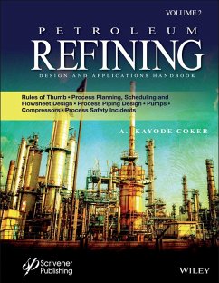
Petroleum Refining Design and Applications Handbook, Volume 2
Rules of Thumb, Process Planning, Scheduling, and Flowsheet Design, Process Piping Design, Pumps, Compressors, and Process Safety Incidents
A. Kayode Coker
Petroleum Refining Design and Applications Handbook, Volume 2
Rules of Thumb, Process Planning, Scheduling, and Flowsheet Design, Process Piping Design, Pumps, Compressors, and Process Safety Incidents
- Gebundenes Buch
- Merkliste
- Auf die Merkliste
- Bewerten Bewerten
- Teilen
- Produkt teilen
- Produkterinnerung
- Produkterinnerung
A must-read for any practicing engineer or student in this area
There is a renaissance that is occurring in chemical and process engineering, and it is crucial for today's scientists, engineers, technicians, and operators to stay current. This book offers the most up-to-date and comprehensive coverage of the most significant and recent changes to petroleum refining, presenting the state-of-the-art to the engineer, scientist, or student. Useful as a textbook, this is also an excellent, handy go-to reference for the veteran engineer, a volume no chemical or process engineering library should be without.…mehr
Andere Kunden interessierten sich auch für
![Petroleum Refining Design and Applications Handbook, Volume 4 Petroleum Refining Design and Applications Handbook, Volume 4]() A. Kayode CokerPetroleum Refining Design and Applications Handbook, Volume 4388,99 €
A. Kayode CokerPetroleum Refining Design and Applications Handbook, Volume 4388,99 €![Petroleum Refining Design and Applications Handbook, Volume 3 Petroleum Refining Design and Applications Handbook, Volume 3]() Petroleum Refining Design and Applications Handbook, Volume 3346,99 €
Petroleum Refining Design and Applications Handbook, Volume 3346,99 €![Petroleum Refining Design and Applications Handbook, Volume 5 Petroleum Refining Design and Applications Handbook, Volume 5]() A. Kayode CokerPetroleum Refining Design and Applications Handbook, Volume 5358,99 €
A. Kayode CokerPetroleum Refining Design and Applications Handbook, Volume 5358,99 €![Introduction to Petroleum Technology Introduction to Petroleum Technology]() James G. SpeightIntroduction to Petroleum Technology111,99 €
James G. SpeightIntroduction to Petroleum Technology111,99 €![Liquid Biofuels Liquid Biofuels]() Liquid Biofuels293,99 €
Liquid Biofuels293,99 €![Coal-Fired Power Generation Handbook Coal-Fired Power Generation Handbook]() James G SpeightCoal-Fired Power Generation Handbook279,99 €
James G SpeightCoal-Fired Power Generation Handbook279,99 €![Formation Testing Formation Testing]() Wilson ChinFormation Testing263,99 €
Wilson ChinFormation Testing263,99 €-
-
-
A must-read for any practicing engineer or student in this area
There is a renaissance that is occurring in chemical and process engineering, and it is crucial for today's scientists, engineers, technicians, and operators to stay current. This book offers the most up-to-date and comprehensive coverage of the most significant and recent changes to petroleum refining, presenting the state-of-the-art to the engineer, scientist, or student. Useful as a textbook, this is also an excellent, handy go-to reference for the veteran engineer, a volume no chemical or process engineering library should be without.
Hinweis: Dieser Artikel kann nur an eine deutsche Lieferadresse ausgeliefert werden.
Produktdetails
- Produktdetails
- Verlag: Wiley & Sons / Wiley-Scrivener
- Artikelnr. des Verlages: 1W119476410
- 1. Auflage
- Seitenzahl: 1056
- Erscheinungstermin: 13. April 2021
- Englisch
- Abmessung: 10mm x 10mm x 10mm
- Gewicht: 454g
- ISBN-13: 9781119476412
- ISBN-10: 1119476410
- Artikelnr.: 49312668
- Herstellerkennzeichnung
- Libri GmbH
- Europaallee 1
- 36244 Bad Hersfeld
- gpsr@libri.de
A. Kayode Coker PhD, is Engineering Consultant for AKC Technology, an Honorary Research Fellow at the University of Wolverhampton, U.K., a former Engineering Coordinator at Saudi Aramco Shell Refinery Company (SASREF) and Chairman of the department of Chemical Engineering Technology at Jubail Industrial College, Saudi Arabia. He has been a chartered chemical engineer for more than 30 years. He is a Fellow of the Institution of Chemical Engineers, U.K. (C. Eng., FIChemE), and a senior member of the American Institute of Chemical Engineers (AIChE). He holds a B.Sc. honors degree in Chemical Engineering, a Master of Science degree in Process Analysis and Development and Ph.D. in Chemical Engineering, all from Aston University, Birmingham, U.K., and a Teacher's Certificate in Education at the University of London, U.K. He has directed and conducted short courses extensively throughout the world and has been a lecturer at the university level. His articles have been published in several international journals. He is an author of six books in chemical engineering, a contributor to the Encyclopedia of Chemical Processing and Design, Vol 61 and a certified train - the mentor trainer. A Technical Report Assessor and Interviewer for chartered chemical engineers (IChemE) in the U.K. He is a member of the International Biographical Centre in Cambridge, U.K. (IBC) as Leading Engineers of the World for 2008. Also, he is a member of International Who's Who of ProfessionalsTM and Madison Who's Who in the U.S.
Preface xv
Acknowledgements xvii
13 Rules of Thumb--Summary 1
13.0 Introduction 1
14 Process Planning, Scheduling, and Flowsheet Design 19
14.1 Introduction 19
14.2 Organizational Structure 20
14.2.1 Process Design Scope 21
14.3 Role of the Process Design Engineer 23
14.4 Computer-Aided Flowsheeting 24
14.5 Flowsheets--Types 26
14.5.1 Block Diagram 26
14.5.2 Process Flowsheet or Flow Diagram 26
14.5.3 Piping Flowsheet or Mechanical Flow Diagram, or Piping and Instrumentation Diagram (P&ID) 27
14.5.4 Combined Process and Piping Flowsheet or Diagram 32
14.5.5 Utility Flowsheets or Diagrams (ULDs) 32
14.5.6 Special Flowsheets or Diagrams 36
14.5.7 Special or Supplemental Aids 36
14.6 Flowsheet Presentation 36
14.7 General Arrangements Guide 36
14.8 Computer-Aided Flowsheet Design/Drafting 38
14.9 Flowsheet Symbols 40
14.10 Line Symbols and Designations 43
14.11 Materials of Construction for Lines 46
14.12 Test Pressure for Lines 47
14.13 Working Schedules 56
14.14 Information Checklists 61
14.15 Basic Engineering and Front End Engineering Design (FEED) 63
References 64
15 Fluid Flow 65
15.1 Introduction 65
15.2 Flow of Fluids in Pipes 65
15.3 Scope 70
15.4 Basis 72
15.5 Incompressible Flow 72
15.6 Compressible Flow: Vapors and Gases 73
15.7 Important Pressure Level References 75
15.8 Factors of "Safety" for Design Basis 75
15.9 Pipe, Fittings, and Valves 75
15.10 Pipe 75
15.11 Total Line Pressure Drop 78
15.11.1 Relationship Between the Pipe Diameter and Pressure Drop (DeltaP) 80
15.11.2 Economic Balance in Piping and Optimum Pipe Diameter 82
15.12 Reynolds Number, Re (Sometimes Used NRe) 83
15.13 Pipe Relative Roughness 85
15.14 Darcy Friction Factor, f 85
15.15 Friction Head Loss (Resistance) in Pipe, Fittings, and Connections 94
15.15.1 Pressure Drop in Straight Pipe: Incompressible Fluid 94
15.16 Oil System Piping 96
15.16.1 Density and Specific Gravity 97
15.16.2 Specific Gravity of Blended Products 98
15.16.3 Viscosity 98
15.16.4 Viscosity of Blended Products 100
15.16.5 Blending Index, H 101
15.16.6 Vapor Pressure 101
15.16.7 Velocity 101
15.16.8 Frictional Pressure Drop, ft of Liquid Head 104
15.16.9 Hazen-Williams Equation 105
15.16.10 Transmission Factor 107
15.16.11 Miller Equation 112
15.16.12 Shell-MIT Equation 113
15.17 Pressure Drop in Fittings, Valves, and Connections 116
15.17.1 Incompressible Fluid 116
15.17.2 Velocity and Velocity Head 116
15.17.3 Equivalent Lengths of Fittings 117
15.17.4 L/D Values in Laminar Region 120
15.17.5 Validity of K Values 122
15.17.6 Laminar Flow 122
15.17.7 Expressing All Pipe Sizes in Terms of One Diameter 124
15.17.8 Loss Coefficient 128
15.17.9 Sudden Enlargement or Contraction 134
15.17.10 For Sudden Contractions 134
15.17.11 Piping Systems 136
15.18 Resistance of Valves 136
15.19 Flow Coefficients for Valves, Cv 137
15.20 Flow Meters 138
15.20.1 Process Design of Orifice Meter 138
15.20.2 Nozzles and Orifices 142
Conclusion 167
15.21 Estimation of Pressure Loss Across C
"...the author is committed to sharing a career's worth of lessons and design experiences, offering clear explanations on individual topics...a useful addition to an experienced engineer's library of information. It could also be extremely helpful to engineering students..."
The Chemical Engineer, November 2021
The Chemical Engineer, November 2021

