- Gebundenes Buch
- Merkliste
- Auf die Merkliste
- Bewerten Bewerten
- Teilen
- Produkt teilen
- Produkterinnerung
- Produkterinnerung
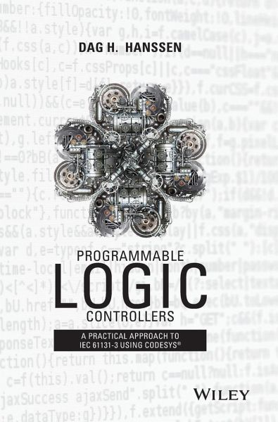
Widely used across industrial and manufacturing automation, Programmable Logic Controllers (PLCs) perform a broad range of electromechanical tasks with multiple input and output arrangements, designed specifically to cope in severe environmental conditions such as automotive and chemical plants.
Andere Kunden interessierten sich auch für
- Terry BordenTechnician's Guide to Programmable Controllers94,99 €
- David JohnsonProgrammable Controllers for Factory Automation80,99 €
- Murat Uzam (Meliksah University, Kayseri, Turkey)Building a Programmable Logic Controller with a Pic16f648a Microcontroller190,99 €
- David RomanoMake: FPGAs27,99 €
- Feynman Lectures on Computation56,99 €
- Stephen P TubbsProgrammable Logic Controller (Plc) Tutorial, Siemens Simatic S7-20044,99 €
- Helen PapagiannisAugmented Human35,99 €
-
-
-
Widely used across industrial and manufacturing automation, Programmable Logic Controllers (PLCs) perform a broad range of electromechanical tasks with multiple input and output arrangements, designed specifically to cope in severe environmental conditions such as automotive and chemical plants.
Hinweis: Dieser Artikel kann nur an eine deutsche Lieferadresse ausgeliefert werden.
Produktdetails
- Produktdetails
- Verlag: John Wiley & Sons Inc
- Seitenzahl: 416
- Erscheinungstermin: 23. November 2015
- Englisch
- Abmessung: 250mm x 175mm x 27mm
- Gewicht: 854g
- ISBN-13: 9781118949245
- ISBN-10: 1118949242
- Artikelnr.: 42774652
- Herstellerkennzeichnung
- Libri GmbH
- Europaallee 1
- 36244 Bad Hersfeld
- 06621 890
Dag H. Hanssen works as an Assistant Professor in automation at the Institute of Engineering and Safety at the University of Tromsø. During the course of his 18 year long career with the university he has taught many different courses, but he now focusses on control technique, process automation and Application Development.
Preface xiv Part One Hardware 1 1 About PLCs 3 1.1 History 4 1.1.1 More Recent Developments 6 1.2 Structure 7 1.2.1 Inputs and Outputs 10 1.3 PLC Operation 13 1.3.1 Process Knowledge 14 1.3.2 Standard Operations 16 1.3.3 Cyclic, Freewheeling, or Event
Controlled Execution 18 1.4 Test Problems 19 2 Digital Signals and Digital Inputs and Outputs 20 2.1 Introduction 20 2.2 Terminology 21 2.2.1 Discrete, Digital, Logical, and Binary 21 2.2.2 Sensors, Transducers, and Transmitters 22 2.3 Switches 24 2.3.1 Limit Switches 24 2.3.2 Safety Devices 24 2.3.3 Magnetic Switches 25 2.4 Logical Sensors 26 2.4.1 Inductive Sensors 27 2.4.2 Capacitive Sensors 29 2.4.3 Photocells 30 2.4.4 Ultrasonic Sensors 33 2.4.5 Rotating Sensors (Encoders) 34 2.4.6 Other Detection Principles and Sensors 37 2.5 Connection of Logical Sensors 39 2.5.1 Sink/Source 41 2.5.2 Selecting a Sensor with the Proper Type of Output 43 2.6 Properties of Discrete Inputs 44 2.7 Discrete Actuators 45 2.7.1 Relays and Contactors 46 2.7.2 Solenoids and Magnetic Valves 47 2.7.3 Transistor Outputs versus Relay Outputs 49 2.8 Test Problems 50 3 Analog Signals and Analog I/O 52 3.1 Introduction 52 3.2 Digitalization of Analog Signals 53 3.2.1 Filtering 53 3.2.2 A/D Conversion 55 3.3 Analog Instrumentation 58 3.3.1 About Sensors 58 3.3.2 Standard Signal Formats 59 3.3.3 On the 4-20 mA Standard 59 3.3.4 Some Other Properties of Sensors 61 3.4 Temperature Sensors 61 3.4.1 Thermocouple 61 3.4.2 PT100/NI1000 62 3.4.3 Thermistors 64 3.5 Connection 64 3.5.1 About Noise, Loss, and Cabling 64 3.5.2 Connecting Sensors 67 3.5.3 Connection of a PT100 (RTD) 68 3.5.4 Connecting Thermocouples 72 3.6 Properties of Analog Input Modules 72 3.6.1 Measurement Ranges and Digitizing: Resolution 72 3.6.2 Important Properties and Parameters 74 3.7 Analog Output Modules and Standard Signal Formats 75 3.8 Test Problems 76 Part Two Methodic 79 4 Structured Design 81 4.1 Introduction 81 4.2 Number Systems 82 4.2.1 The Decimal Number Systems 82 4.2.2 The Binary Number System 82 4.2.3 The Hexadecimal Number System 83 4.2.4 Binary
Coded Decimal Numbers 85 4.2.5 Conversion between Number Systems 86 4.3 Digital Logic 87 4.4 Boolean Design 91 4.4.1 Logical Functional Expressions 91 4.4.2 Boolean Algebra 93 4.5 Sequential Design 97 4.5.1 Flowchart 97 4.5.2 Example: Flowchart for Mixing Process 99 4.5.3 Example: Flowchart for an Automated Packaging Line 101 4.5.4 Sequence Diagrams 107 4.5.5 Example: Sequence Diagram for the Mixing Process 110 4.5.6 Example: Batch Process 112 4.6 State
Based Design 113 4.6.1 Why Use State Diagrams? 114 4.6.2 State Diagrams 114 4.6.3 Example: Batch Process 117 4.6.4 Example: Level Process 118 4.6.5 Example: Packing Facility for Apples 121 4.7 Summary 124 4.8 Test Problems 125 Part Three IEC 61131
3 131 5 Introduction to Programming and IEC 61131
3 133 5.1 Introduction 133 5.1.1 Weaknesses in Traditional PLCs 134 5.1.2 Improvements with IEC 61131
3 136 5.1.3 On Implementation of the Standard 137 5.2 Brief Presentation of the Languages 138 5.2.1 ST 138 5.2.2 FBD 138 5.2.3 LD 139 5.2.4 IL 139 5.2.5 SFC 141 5.3 Program Structure in IEC 61131
3 141 5.3.1 Example of a Configuration 145 5.4 Program Processing 146 5.4.1 Development of Programming Languages 146 5.4.2 From Source Code to Machine Code 147 5.5 Test Problems 151 6 IEC 61131
3: Common Language Elements 152 6.1 Introduction 152 6.2 Identifiers, Keywords, and Comments 153 6.2.1 Identifiers 153 6.2.2 Keywords 154 6.2.3 Comments 154 6.3 About Variables and Data Types 156 6.4 Pragmas and Literals 156 6.4.1 Literal 157 6.5 Data Types 158 6.5.1 Numerical and Binary Data Types 158 6.5.2 Data Types for Time and Duration 161 6.5.3 Text Strings 163 6.5.4 Generic Data Types 164 6.5.5 User
Defined Data Types 166 6.6 Variables 169 6.6.1 Conventional Addressing 170 6.6.2 Declaration of Variables with IEC 61131
3 171 6.6.3 Local Versus Global Variables 174 6.6.4 Input and Output Variables 175 6.6.5 Other Variable Types 176 6.7 Direct Addressing 176 6.7.1 Addressing Structure 176 6.7.2 I/O
Addressing 178 6.8 Variable versus I/O
Addresses 179 6.8.1 Unspecified I/O
Addresses 179 6.9 Declaration of Multielement Variables 180 6.9.1 Arrays 181 6.9.2 Data Structures 182 6.10 Test Problems 184 7 Functions 187 7.1 Introduction 187 7.2 On Functions 188 7.3 Standard Functions 189 7.3.1 Assignment 190 7.4 Boolean Operations 191 7.5 Arithmetic Functions 192 7.5.1 Overflow 193 7.6 Comparison 194 7.7 Numerical Operations 195 7.7.1 Priority of Execution 196 7.8 Selection 197 7.9 Type Conversion 197 7.10 Bit
String Functions 199 7.11 Text
String Functions 200 7.12 Defining New Functions 202 7.13 EN/ENO 203 7.14 Test Problems 204 8 Function Blocks 206 8.1 Introduction 206 8.1.1 The Standard's FBs 207 8.2 Declaring and Calling FBs 207 8.3 FBs for Flank Detection 208 8.4 Bistable Elements 209 8.5 Timers 210 8.6 Counters 211 8.6.1 Up
Counter 212 8.6.2 Down
Counter 212 8.6.3 Up/Down
Counter 212 8.7 Defining New FBs 213 8.7.1 Encapsulation of Code 214 8.7.2 Other Nonstandardized FBs 216 8.8 Programs 217 8.8.1 Program Calls 218 8.8.2 Execution Control 219 8.9 Test Problems 220 Part Four Programming 221 9 Ladder Diagram (LD) 223 9.1 Introduction 223 9.2 Program Structure 224 9.2.1 Contacts and Conditions 225 9.2.2 Coils and Actions 226 9.2.3 Graphical Elements: An Overview 227 9.3 Boolean Operations 227 9.3.1 AND/OR
Conditions 227 9.3.2 Set/Reset Coils 230 9.3.3 Edge Detecting Contacts 233 9.3.4 Example: Control of a Mixing Process 234 9.4 Rules for Execution 237 9.4.1 One Output: Several Conditions 237 9.4.2 The Importance of the Order of Execution 238 9.4.3 Labels and Jumps 239 9.5 Use of Standard Functions in LD 240 9.6 Development and Use of FBs in LD 242 9.7 Structured Programming in LD 244 9.7.1 Flowchart versus RS
Based LD Code 248 9.7.2 State Diagrams versus RS
Based LD Code 253 9.8 Summary 259 9.9 Test Problems 260 10 Function Block Diagram (FBD) 262 10.1 Introduction 262 10.2 Program Structure 263 10.2.1 Concepts 264 10.3 Execution Order and Loops 264 10.3.1 Labels and Jumps 265 10.4 User
Defined Functions and FBs 266 10.5 Integer Division 268 10.6 Sequential Programming with FBD 271 10.7 Test Problems 273 11 Structured Text (ST) 278 11.1 Introduction 278 11.2 ST in General 279 11.2.1 Program Structure 280 11.3 Standard Functions and Operators 281 11.3.1 Assignment 282 11.4 Calling FBs 283 11.4.1 Flank Detection and Memories 284 11.4.2 Timers 287 11.4.3 Counters 288 11.5 IF Statements 288 11.6 CASE Statements 290 11.7 ST Code Based upon State Diagrams 292 11.7.1 Example: Code for the Level Process 295 11.8 Loops 298 11.8.1 WHILE ... DO... END_WHILE 298 11.8.2 FOR ... END_FOR 299 11.8.3 REPEAT ... END_REPEAT 300 11.8.4 The EXIT Instruction 300 11.9 Example: Defining and Calling Functions 301 11.10 Test Problems 302 12 Sequential Function Chart (SFC) 306 12.1 Introduction 306 12.1.1 SFC in General 307 12.2 Structure and Graphics 307 12.2.1 Overview: Graphic Symbols 309 12.2.2 Alternative Branches 309 12.2.3 Parallel Branches 311 12.3 Steps 312 12.3.1 Step Addresses 313 12.3.2 SFC in Text Form (for Those Specially Interested...) 314 12.4 Transitions 314 12.4.1 Alternative Definition of Transitions 315 12.5 Actions 317 12.5.1 Action Types 318 12.5.2 Action Control 319 12.5.3 Alternative Declaration and Use of Actions 321 12.6 Control of Diagram Execution 322 12.7 Good Design Technique 323 12.8 Test Problems 326 13 Examples 331 13.1 Example 1: PID Controller Function Block: Structured Text 331 13.2 Example 2: Sampling: SFC 333 13.2.1 List of Variables 334 13.2.2 Possible Solution 334 13.3 Example 3: Product Control: SFC 337 13.3.1 Functional Description 338 13.3.2 List of Variables 338 13.3.3 Possible Solution 339 13.4 Example 4: Automatic Feeder: ST/SFC/FBD 342 13.4.1 Planning and Structuring 344 13.4.2 Alternative 1: SFC 345 13.4.3 Alternative 2: ST/FBD 347 Part Five Implementation 351 14 CODESYS 2.3 353 14.1 Introduction 353 14.2 Starting the Program 354 14.2.1 The Contents of a Project 356 14.3 Configuring the (WAGO) PLC 357 14.4 Communications with the PLC 360 14.4.1 The Gateway Server 361 14.4.2 Local Connection via Service Cable 362 14.4.3 Via Ethernet 363 14.4.4 Communication with a PLC Connected to a Remote PC 364 14.4.5 Testing Communications 365 14.5 Libraries 365 14.6 Defining a POU 367 14.7 Programming in FBD/LD 368 14.7.1 Declaring Variables 369 14.7.2 Programming with FBD 371 14.7.3 Programming with LD 372 14.8 Configuring Tasks 375 14.9 Downloading and Testing Programs 376 14.9.1 Debugging 377 14.10 Global Variables and Special Data Types 379 15 CODESYS Version 3.5 381 15.1 Starting a New Project 381 15.1.1 Device 382 15.1.2 Application 384 15.2 Programming and Programming Units (POUs) 386 15.2.1 Declaration of Variables 388 15.3 Compiling and Running the Project 389 15.3.1 Start Gateway Server and PLS and Set Up Communications 390 15.4 Test Problems 393 Bibliography 395 Index 396