- Gebundenes Buch
- Merkliste
- Auf die Merkliste
- Bewerten Bewerten
- Teilen
- Produkt teilen
- Produkterinnerung
- Produkterinnerung
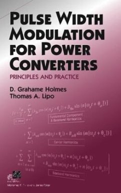
The design of inverters employing Pulse Width Modulation (PWM) to vary the voltage and amplitude of power electronic inverters has evolved over the past forty years. This is the first comprehensive textbook to view the subject as a whole and to clarify and unify the many diverse approaches taken by researchers.
The first single volume resource for researchers in the field who previously had to depend on separate papers and conference records to attain a working knowledge of the subject. Brings together the field s diverse approaches into an integrated and comprehensive theory of PWM
Andere Kunden interessierten sich auch für
![Advanced Pulse-Width-Modulation: With Freedom to Optimize Power Electronics Converters Advanced Pulse-Width-Modulation: With Freedom to Optimize Power Electronics Converters]() Dong JiangAdvanced Pulse-Width-Modulation: With Freedom to Optimize Power Electronics Converters119,99 €
Dong JiangAdvanced Pulse-Width-Modulation: With Freedom to Optimize Power Electronics Converters119,99 €![PULSE WIDTH MODULATION IN POWER ELECTRONICS PULSE WIDTH MODULATION IN POWER ELECTRONICS]() Isaak Mayergoyz & Siddharth TyagiPULSE WIDTH MODULATION IN POWER ELECTRONICS158,99 €
Isaak Mayergoyz & Siddharth TyagiPULSE WIDTH MODULATION IN POWER ELECTRONICS158,99 €![Advanced Pulse-Width-Modulation: With Freedom to Optimize Power Electronics Converters Advanced Pulse-Width-Modulation: With Freedom to Optimize Power Electronics Converters]() Dong JiangAdvanced Pulse-Width-Modulation: With Freedom to Optimize Power Electronics Converters86,99 €
Dong JiangAdvanced Pulse-Width-Modulation: With Freedom to Optimize Power Electronics Converters86,99 €![Pulse Width Modulated DC-DC Converters Pulse Width Modulated DC-DC Converters]() Keng Chih WuPulse Width Modulated DC-DC Converters112,99 €
Keng Chih WuPulse Width Modulated DC-DC Converters112,99 €![Pulse Width Modulated DC-DC Converters Pulse Width Modulated DC-DC Converters]() Keng Chih WuPulse Width Modulated DC-DC Converters112,99 €
Keng Chih WuPulse Width Modulated DC-DC Converters112,99 €![Advanced Pulse Width Modulation Controller ICs for DC-DC Converters Advanced Pulse Width Modulation Controller ICs for DC-DC Converters]() Jianhui ZhangAdvanced Pulse Width Modulation Controller ICs for DC-DC Converters38,99 €
Jianhui ZhangAdvanced Pulse Width Modulation Controller ICs for DC-DC Converters38,99 €![Laboratory Manual for Pulse-Width Modulated DC-DC Power Converters Laboratory Manual for Pulse-Width Modulated DC-DC Power Converters]() Marian K KazimierczukLaboratory Manual for Pulse-Width Modulated DC-DC Power Converters83,99 €
Marian K KazimierczukLaboratory Manual for Pulse-Width Modulated DC-DC Power Converters83,99 €-
-
-
The design of inverters employing Pulse Width Modulation (PWM) to vary the voltage and amplitude of power electronic inverters has evolved over the past forty years. This is the first comprehensive textbook to view the subject as a whole and to clarify and unify the many diverse approaches taken by researchers.
The first single volume resource for researchers in the field who previously had to depend on separate papers and conference records to attain a working knowledge of the subject.
Brings together the field s diverse approaches into an integrated and comprehensive theory of PWM
Hinweis: Dieser Artikel kann nur an eine deutsche Lieferadresse ausgeliefert werden.
Produktdetails
- Produktdetails
- IEEE Series on Power Engineering
- Verlag: IEEE Press / Wiley & Sons
- 1. Auflage
- Seitenzahl: 744
- Erscheinungstermin: 14. Oktober 2003
- Englisch
- Abmessung: 246mm x 155mm x 39mm
- Gewicht: 1154g
- ISBN-13: 9780471208143
- ISBN-10: 0471208140
- Artikelnr.: 11096385
- Herstellerkennzeichnung
- Libri GmbH
- Europaallee 1
- 36244 Bad Hersfeld
- gpsr@libri.de
D. GRAHAME HOLMES is a professor in the Department of Electrical and Computer Systems Engineering at Monash University, Australia. THOMAS A. LIPO is a professor in the Department of Electrical and Computer Engineering at the University of Wisconsin-Madison.
Preface.
Acknowledgments.
Nomenclature.
Chapter 1: Introduction to Power Electronic Converters.
1.1 Basic Converter Topologies.
1.2 Voltage Source/Stiff Inverters.
1.3 Switching Function Representation of Three-Phase Converters.
1.4 Output Voltage Control.
1.5 Current Source/Stiff Inverters.
1.6 Concept of a Space Vector.
1.7 Three-Level Inverters.
1.8 Multilevel Inverter Topologies.
1.9 Summary.
Chapter 2: Harmonic Distortion.
2.1 Harmonic Voltage Distortion Factor.
2.2 Harmonic Current Distortion Factor.
2.3 Harmonic Distortion Factors for Three-Phase Inverters.
2.4 Choice of Performance Indicator.
2.5 WTHD of Three-Level Inverter.
2.6 The Induction Motor Load.
2.7 Harmonic Distortion Weighting Factors for Induction Motor Load.
2.8 Example Calculation of Harmonic Losses.
2.9 WTHD Normalization for PWM Inverter Supply.
2.10 Summary.
Chapter 3: Modulation of One Inverter Phase Leg.
3.1 Fundamental Concepts of PWM.
3.2 Evaluation of PWM Schemes.
3.3 Double Fourier Integral Analysis of a Two-Level Pulse Width-Modulated
Waveform.
3.4 Naturally Sampled Pulse Width Modulation.
3.5 PWM Analysis by Duty Cycle Variation.
3.6 Regular Sampled Pulse Width Modulation.
3.7 "Direct" Modulation.
3.8 Integer versus Non-Integer Frequency Ratios.
3.9 Review of PWM Variations.
3.10 Summary.
Chapter 4: Modulation of Single-Phase Voltage Source Inverters.
4.1 Topology of a Single-Phase Inverter.
4.2 Three-Level Modulation of a Single-Phase Inverter.
4.3 Analytic Calculation of Harmonic Losses.
4.4 Sideband Modulation.
4.5 Switched Pulse Position.
4.6 Switched Pulse Sequence.
4.7 Summary.
Chapter 5: Modulation of Three-Phase Voltage Source Inverters.
5.1 Topology of a Three-Phase Inverter (VSI).
5.2 Three-Phase Modulation with Sinusoidal References.
5.3 Third-Harmonic Reference Injection.
5.4 Analytic Calculation of Harmonic Losses.
5.5 Discontinuous Modulation Strategies.
5.6 Triplen Carrier Ratios and Subharmonics.
5.7 Summary.
Chapter 6: Zero Space Vector Placement Modulation Strategies.
6.1 Space Vector Modulation.
6.1.1 Principles of Space Vector Modulation.
6.1.2 SVM Compared to Regular Sampled PWM.
6.2 Phase Leg References for Space Vector Modulation.
6.3 Naturally Sampled SVM.
6.4 Analytical Solution for SVM.
6.5 Harmonic Losses for SVM.
6.6 Placement of the Zero Space Vector.
6.7 Discontinuous Modulation.
6.8 Phase Leg References for Discontinuous PWM.
6.9 Analytical Solutions for Discontinuous PWM.
6.10 Comparison of Harmonic Performance.
6.11 Harmonic Losses for Discontinuous PWM.
6.12 Single-Edge SVM.
6.13 Switched Pulse Sequence.
6.14 Summary.
Chapter 7: Modulation of Current Source Inverters.
7.1 Three-Phase Modulators as State Machines.
7.2 Naturally Sampled CSI Space Vector Modulator.
7.3 Experimental Confirmation.
7.4 Summary.
Chapter 8: Overmodulation of an Inverter.
8.1 The Overmodulation Region.
8.2 Naturally Sampled Overmodulation of One Phase Leg of an Inverter.
8.3 Regular Sampled Overmodulation of One Phase Leg of an Inverter.
8.4 Naturally Sampled Overmodulation of Single- and Three-Phase Inverters.
8.5 PWM Controller Gain during Overmodulation.
8.6 Space Vector Approach to Overmodulation.
8.7 Summary.
Chapter 9: Programmed Modulation Strategies.
9.1 Optimized Space Vector Modulation.
9.2 Harmonic Elimination PWM.
9.3 Performance Index for Optimality.
9.4 Optimum PWM.
9.5 Minimum-Loss PWM.
9.6 Summary.
Chapter 10: Programmed Modulation of Multilevel Converters.
10.1 Multilevel Converter Alternatives.
10.2 Block Switching Approaches to Voltage Control.
10.3 Harmonic Elimination Applied to Multilevel Inverters.
10.4 Minimum Harmonic Distortion.
10.5 Summary.
Chapter 11: Carrier-Based PWM of Multilevel Inverters.
11.1 PWM of Cascaded Single-Phase H-Bridges.
11.2 Overmodulation of Cascaded H-Bridges.
11.3 PWM Alternatives for Diode-Clamped Multilevel Inverters.
11.4 Three-Level Naturally Sampled PD PWM.
11.5 Three-Level Naturally Sampled APOD or POD PWM.
11.6 Overmodulation of Three-Level Inverters.
11.7 Five-Level PWM for Diode-Clamped Inverters.
11.8 PWM of Higher Level Inverters.
11.9 Equivalent PD PWM for Cascaded Inverters.
11.10 Hybrid Multilevel Inverter.
11.11 Equivalent PD PWM for a Hybrid Inverter.
11.12 Third-Harmonic Injection for Multilevel Inverters.
11.13 Operation of a Multilevel Inverter with a Variable Modulation Index.
11.14 Summary.
Chapter 12: Space Vector PWM for Multilevel Converters.
12.1 Optimized Space Vector Sequences.
12.2 Modulator for Selecting Switching States.
12.3 Decomposition Method.
12.4 Hexagonal Coordinate System.
12.5 Optimal Space Vector Position within a Switching Period.
12.6 Comparison of Space Vector PWM to Carrier-Based PWM.
12.7 Discontinuous Modulation in Multilevel Inverters.
12.8 Summary.
Chapter 13: Implementation of a Modulation Controller.
13.1 Overview of a Power Electronic Conversion System.
13.2 Elements of a PWM Converter System.
13.3 Hardware Implementation of the PWM Process.
13.4 PWM Software Implementation.
13.5 Summary.
Chapter 14: Continuing Developments in Modulation.
14.1 Random Pulse Width Modulation.
14.2 PWM Rectifier with Voltage Unbalance.
14.3 Common Mode Elimination.
14.4 Four Phase Leg Inverter Modulation.
14.5 Effect of Minimum Pulse Width.
14.6 PWM Dead-Time Compensation.
14.7 Summary.
Appendix 1: Fourier Series Representation of a Double Variable Controlled
Waveform.
Appendix 2: Jacobi-Anger and Bessel Function Relationships.
A2.1 Jacobi-Anger Expansions.
A2.2 Bessel Function Integral Relationships.
Appendix 3: Three-Phase and Half-Cycle Symmetry Relationships.
Appendix 4: Overmodulation of a Single-Phase Leg.
A4.1 Naturally Sampled Double-Edge PWM.
A4.2 Symmetric Regular Sampled Double-Edge PWM.9
A4.3 Asymmetric Regular Sampled Double-Edge PWM.
Appendix 5: Numeric Integration of a Double Fourier Series Representation
of a Switched Waveform.
A5.1 Formulation of the Double Fourier Integral.
A5.2 Analytical Solution of the Inner Integral.
A5.3 Numeric Integration of the Outer Integral.
Bibliography.
Index.

