W. A. Davis
Radio Frequency Circuit Design
W. A. Davis
Radio Frequency Circuit Design
- Gebundenes Buch
- Merkliste
- Auf die Merkliste
- Bewerten Bewerten
- Teilen
- Produkt teilen
- Produkterinnerung
- Produkterinnerung
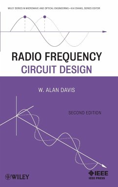
This book focuses on components such as filters, transformers, amplifiers, mixers, and oscillators. Even the phase lock loop chapter (the last in the book) is oriented toward practical circuit design, in contrast to the more systems orientation of most communication texts.
Andere Kunden interessierten sich auch für
![RF Circuit Design 2e RF Circuit Design 2e]() Richard Chi-Hsi LiRF Circuit Design 2e183,99 €
Richard Chi-Hsi LiRF Circuit Design 2e183,99 €![Fundamentals of RF Circuit Design Fundamentals of RF Circuit Design]() Jeremy EverardFundamentals of RF Circuit Design149,99 €
Jeremy EverardFundamentals of RF Circuit Design149,99 €![Advanced Circuits Advanced Circuits]() Krzysztof IniewskiAdvanced Circuits171,99 €
Krzysztof IniewskiAdvanced Circuits171,99 €![Bandpass Filters Bandpass Filters]() Lei ZhuBandpass Filters140,99 €
Lei ZhuBandpass Filters140,99 €![Microwave and Millimeter Wave Circuits and Systems Microwave and Millimeter Wave Circuits and Systems]() Apostolos GeorgiadisMicrowave and Millimeter Wave Circuits and Systems138,99 €
Apostolos GeorgiadisMicrowave and Millimeter Wave Circuits and Systems138,99 €![Compact Multifunctional Antennas for Wireless Systems Compact Multifunctional Antennas for Wireless Systems]() Eng H. LimCompact Multifunctional Antennas for Wireless Systems119,99 €
Eng H. LimCompact Multifunctional Antennas for Wireless Systems119,99 €![Modeling and Design Techniques for RF Power Amplifiers Modeling and Design Techniques for RF Power Amplifiers]() Arvind RaghavanModeling and Design Techniques for RF Power Amplifiers112,99 €
Arvind RaghavanModeling and Design Techniques for RF Power Amplifiers112,99 €-
-
-
This book focuses on components such as filters, transformers, amplifiers, mixers, and oscillators. Even the phase lock loop chapter (the last in the book) is oriented toward practical circuit design, in contrast to the more systems orientation of most communication texts.
Hinweis: Dieser Artikel kann nur an eine deutsche Lieferadresse ausgeliefert werden.
Hinweis: Dieser Artikel kann nur an eine deutsche Lieferadresse ausgeliefert werden.
Produktdetails
- Produktdetails
- Wiley Series in Microwave and Optical Engineering Vol.1
- Verlag: Wiley & Sons
- 2. Aufl.
- Seitenzahl: 424
- Erscheinungstermin: 28. Dezember 2010
- Englisch
- Abmessung: 240mm x 161mm x 27mm
- Gewicht: 792g
- ISBN-13: 9780470575079
- ISBN-10: 0470575077
- Artikelnr.: 30365867
- Herstellerkennzeichnung
- Libri GmbH
- Europaallee 1
- 36244 Bad Hersfeld
- gpsr@libri.de
The General Editor of the Statistics without Mathematics series at Vor Press is a researcher and data analyst with experience in government, business and the third sector, who is also well-known as an internationally published author of books on statistical testing.
Preface to the Second Edition.
Preface to the First Edition.
1 Information Transfer Technology.
1.1 Introduction.
1.2 Information and Capacity.
1.3 Dependent States.
1.4 Basic Transmitter?Receiver Confi guration.
1.5 Active Device Technology.
Problems.
Reference.
2 Resistors, Capacitors, and Inductors.
2.1 Introduction.
2.2 Resistors.
2.3 Capacitors.
2.4 Inductors.
2.5 Conclusions.
Problems.
References.
3 Impedance Matching.
3.1 Introduction.
3.2 The Q Factor.
3.3 Resonance and Bandwidth.
3.4 Unloaded Q.
3.5 L Circuit Impedance Matching.
3.6 ¿ Transformation Circuit.
3.7 T Transformation Circuit.
3.8 Tapped Capacitor Transformer.
3.9 Parallel Double-Tuned Transformer.
3.10 Conclusions.
Problems.
References.
4 Multiport Circuit Parameters and Transmission Lines.
4.1 Voltage?Current Two-Port Parameters.
4.2 ABCD Parameters.
4.3 Image Impedance.
4.4 Telegrapher's Equations.
4.5 Transmission Line Equation.
4.6 Smith Chart.
4.7 Transmission Line Stub Transformer.
4.8 Commonly Used Transmission Lines.
4.9 Scattering Parameters.
4.10 Indefinite Admittance Matrix.
4.11 Indefinite Scattering Matrix.
4.12 Conclusions.
Problems.
References.
5 Filter Design and Approximation.
5.1 Introduction.
5.2 Ideal and Approximate Filter Types.
5.3 Transfer Function and Basic Filter Concepts.
5.4 Ladder Network Filters.
5.5 Elliptic Filter.
5.6 Matching Between Unequal Resistance Levels.
5.7 Conclusions.
Problems.
References.
6 Transmission Line Transformers.
6.1 Introduction.
6.2 Ideal Transmission Line Transformers.
6.3 Transmission Line Transformer Synthesis.
6.4 Electrically Long Transmission Line Transformers.
6.5 Baluns.
6.6 Dividers and Combiners.
6.7 The 90° Coupler.
Problems.
References.
7 Noise in RF Amplifiers.
7.1 Sources of Noise.
7.2 Thermal Noise.
7.3 Shot Noise.
7.4 Noise Circuit Analysis.
7.5 Amplifier Noise Characterization.
7.6 Noise Measurement.
7.7 Noisy Two-Port Circuits.
7.8 Two-Port Noise Factor Derivation.
7.9 Fukui Noise Model for Transistors.
Problems.
References.
8 Class A Amplifiers.
8.1 Introduction.
8.2 Defi nitions of Gain.
8.3 Transducer Power Gain of a Two-Port Network.
8.4 Power Gain Using S Parameters.
8.5 Simultaneous Match for Maximum Power Gain.
8.6 Stability.
8.7 Class A Power Amplifiers.
8.8 Power Combining of Power Amplifiers.
8.9 Properties of Cascaded Amplifiers.
8.10 Amplifier Design for Optimum Gain and Noise.
8.11 Conclusions.
Problems.
References.
9 RF Power Amplifiers.
9.1 Transistor Configurations.
9.2 Class B Amplifier.
9.3 Class C Amplifier.
9.4 Class C Input Bias Voltage.
9.5 Class D Power Amplifier.
9.6 Class E Power Amplifier.
9.7 Class F Power Amplifier.
9.8 Feed-Forward Amplifiers.
9.9 Conclusions.
Problems.
References.
10 Oscillators and Harmonic Generators.
10.1 Oscillator Fundamentals.
10.2 Feedback Theory.
10.3 Two-Port Oscillators with External Feedback.
10.4 Practical Oscillator Example.
10.5 Minimum Requirements of the Reflection Coefficient.
10.6 Common Gate (Base) Oscillators.
10.7 Stability of an Oscillator.
10.8 Injection-Locked Oscillator.
10.9 Oscillator Phase Noise.
10.10 Harmonic Generators.
Problems.
References.
11 RF Mixers.
11.1 Nonlinear Device Characteristics.
11.2 Figures of Merit for Mixers.
11.3 Single-Ended Mixers.
11.4 Single-Balanced Mixers.
11.5 Double-Balanced Mixers.
11.6 Double-Balanced Transistor Mixers.
11.7 Spurious Response.
11.8 Single-Sideband Noise Factor and Noise Temperature.
11.9 Special Mixer Applications.
11.10 Conclusions.
Problems.
References.
12 Phase-Lock Loops.
12.1 Introduction.
12.2 PLL Design Background.
12.3 PLL Applications.
12.4 PLL Basics.
12.5 Loop Design Principles.
12.6 Linear Analysis of the PLL.
12.7 Locking a Phase-Lock Loop.
12.8 Loop Types.
12.9 Negative Feedback in a PLL.
12.10 PLL Design Equations.
12.11 Phase Detector Types.
12.12 Design Examples.
12.13 Conclusions.
Problems.
References.
Appendix A Example of a Solenoid Design.
Appendix B Analytical Spiral Inductor Model.
Appendix C Double-Tuned Matching Circuit Example.
Appendix D Two-Port Parameter Conversion.
Appendix E Termination of a Transistor Port with a Load.
Appendix F Transistor and Amplifier Formulas.
Appendix G Transformed Frequency-Domain Measurements Using SPICE.
Appendix H Single-Tone Intermodulation Distortion Suppression for
Double-Balanced Mixers.
Index.
"This book focuses on components such as filters, transformers, amplifiers, mixers and oscillators. Even the phase lock loop chapter (the last in the book) is oriented toward practical circuit design, in contrast to the more systems orientation of most communication texts. " (Forums Digital Media Net, 15 March 2011)

