Some 200 years after the original invention, the internal design of a Stirling engine has come to be considered a specialist task, calling for extensive experience and for access to sophisticated computer modelling. The low parts-count of the type is negated by the complexity of the gas processes by which heat is converted to work. The design is perceived as problematic largely because those interactions are neither intuitively evident, nor capable of being made visible by laboratory experiment. There can be little doubt that the situation stands in the way of wider application of this elegant…mehr
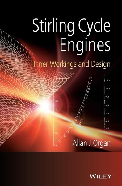
Some 200 years after the original invention, the internal design of a Stirling engine has come to be considered a specialist task, calling for extensive experience and for access to sophisticated computer modelling. The low parts-count of the type is negated by the complexity of the gas processes by which heat is converted to work. The design is perceived as problematic largely because those interactions are neither intuitively evident, nor capable of being made visible by laboratory experiment. There can be little doubt that the situation stands in the way of wider application of this elegant concept. Stirling Cycle Engines re-visits the design challenge, doing so in three stages. Firstly, unrealistic expectations are dispelled: chasing the Carnot efficiency is a guarantee of disappointment, since the Stirling engine has no such pretentions. Secondly, no matter how complex the gas processes, they embody a degree of intrinsic similarity from engine to engine. Suitably exploited, this means that a single computation serves for an infinite number of design conditions. Thirdly, guidelines resulting from the new approach are condensed to high-resolution design charts - nomograms. Appropriately designed, the Stirling engine promises high thermal efficiency, quiet operation and the ability to operate from a wide range of heat sources. Stirling Cycle Engines offers tools for expediting feasibility studies and for easing the task of designing for a novel application. Key features: * Expectations are re-set to realistic goals. * The formulation throughout highlights what the thermodynamic processes of different engines have in common rather than what distinguishes them. * Design by scaling is extended, corroborated, reduced to the use of charts and fully Illustrated. * Results of extensive computer modelling are condensed down to high-resolution Nomograms. * Worked examples feature throughout. Prime movers (and coolers) operating on the Stirling cycle are of increasing interest to industry, the military (stealth submarines) and space agencies. Stirling Cycle Engines fills a gap in the technical literature and is a comprehensive manual for researchers and practitioners. In particular, it will support effort world-wide to exploit the potential for such applications as small-scale CHP (combined heat and power), solar energy conversion and the utilization of low-grade heat.Hinweis: Dieser Artikel kann nur an eine deutsche Lieferadresse ausgeliefert werden.
Allan J. Organ, formerly of University of Cambridge, UK - now retired. Before his retirement Allan J. Organ was a lecturer at the University of Cambridge, specializing in thermodynamics and gas dynamics of the Stirling cycle machine and regenerator.He has studied stirling cycle machines throughout his career and is a leading authority in the field. As well as his teaching work, he has acted as a consultant in this area for numerous companies including Hymatic Ltd, Premier Precision Ltd, Lucas Aerospace Ltd, British Aerospace PLC, as well as for the Ministry of Defense.
Inhaltsangabe
About the Author xi Foreword xiii Preface xvii Notation xix 1 Stirling myth - and Stirling reality 1 1.1 Expectation 1 1.2 Myth by myth 2 1.3 ...and some heresy 7 1.4 Why this crusade? 7 2 R eflexions sur le cicle de Carnot 9 2.1 Background 9 2.2 Carnot re-visited 10 2.3 Isothermal cylinder 11 2.4 Specimen solutions 14 2.5 'Realistic' Carnot cycle 16 2.6 'Equivalent' polytropic index 16 2.7 R eflexions 17 3 What Carnot efficiency? 19 3.1 Epitaph to orthodoxy 19 3.2 Putting Carnot to work 19 3.3 Mean cycle temperature difference, Tx = T - Tw 20 3.4 Net internal loss by inference 21 3.5 Why no p-V diagram for the 'ideal' Stirling cycle? 23 3.6 The way forward 23 4 Equivalence conditions for volume variations 25 4.1 Kinematic configuration 25 4.2 'Additional' dead space 27 4.3 Net swept volume 32 5 The optimum versus optimization 33 5.1 An engine from Turkey rocks the boat 33 5.2 ...and an engine from Duxford 34 5.3 Schmidt on Schmidt 36 5.4 Crank-slider mechanism again 41 5.5 Implications for engine design in general 42 6 Steady-flow heat transfer correlations 45 6.1 Turbulent - or turbulent? 45 6.2 Eddy dispersion time 47 6.3 Contribution from 'inverse modelling' 48 6.4 Contribution from Scaling 50 6.5 What turbulence level? 52 7 A question of adiabaticity 55 7.1 Data 55 7.2 The Archibald test 55 7.3 A contribution from Newton 56 7.4 Variable-volume space 57 7.5 D esax e 59 7.6 Thermal diffusion - axi-symmetric case 60 7.7 Convection versus diffusion 61 7.8 Bridging the gap 61 7.9 Interim deductions 64 8 More adiabaticity 65 8.1 'Harmful' dead space 65 8.2 'Equivalent' steady-flow closed-cycle regenerative engine 66 8.3 'Equivalence' 68 8.4 Simulated performance 68 8.5 Conclusions 70 8.6 Solution algorithm 71 9 Dynamic Similarity 73 9.1 Dynamic similarity 73 9.2 Numerical example 75 9.3 Corroboration 79 9.4 Transient response of regenerator matrix 80 9.5 Second-order effects 82 9.6 Application to reality 82 10 Intrinsic Similarity 83 10.1 Scaling and similarity 83 10.2 Scope 83 10.3 First steps 88 10.4 ...without the computer 90 11 Getting started 97 11.1 Configuration 97 11.2 Slots versus tubes 98 11.3 The 'equivalent' slot 102 11.4 Thermal bottleneck 104 11.5 Available work lost - conventional arithmetic 107 12 FastTrack gas path design 109 12.1 Introduction 109 12.2 Scope 110 12.3 Numerical example 110 12.4 Interim comment 118 12.5 Rationale behind FastTrack 118 12.6 Alternative start point - GPU-3 charged with He 121 13 FlexiScale 129 13.1 FlexiScale? 129 13.2 Flow path dimensions 130 13.3 Operating conditions 133 13.4 Regenerator matrix 137 13.5 Rationale behind FlexiScale 137 14 ReScale 141 14.1 Introduction 141 14.2 Worked example step-by-step 141 14.3 Regenerator matrix 145 14.4 Rationale behind ReScale 145 15 Less steam, more traction - Stirling engine design without the hot air 149 15.1 Optimum heat exchanger 149 15.2 Algebraic development 150 15.3 Design sequence 153 15.4 Note of caution 159 16 Heat transfer correlations - from the horse's mouth 163 16.1 The time has come 163 16.2 Application to design 166 16.3 Rationale behind correlation parameters RE and XQXE 167 17 Wire-mesh regenerator - 'back of envelope' sums 171 17.1 Status quo 171 17.2 Temperature swing 171 17.3 Aspects of flow design 173 17.4 A thumb-nail sketch of transient response 181 17.5 Wire diameter 184 17.6 More on intrinsic similarity 190 18 Son of Schmidt 199 18.1 Situations vacant 199 18.2 Analytical opportunities waiting to be explored 200 18.3 Heat exchange - arbitrary wall temperature gradient 201 18.4 Defining equations and discretization 205 18.5 Specimen implementation 206 18.6 Integration 208 18.7 Specimen temperature solutions 211 19 H2 versus He versus air 215 19.1 Conventional wisdom 215 19.2 Further enquiry 216 19.3 So, why air? 217 20 The 'hot air' engine 219 20.1 In praise of arithmetic 219 20.2 Reynolds number Re in the annular gap 222 20.3 Contact surface temperature in annular gap 223 20.4 Design parameter Ld Mg 225 20.5 Building a specification 226 20.6 Design step by step 228 20.7 Gas path dimensions 229 20.8 Caveat 234 21 Ultimate Lagrange formulation? 235 21.1 Why a new formulation? 235 21.2 Context 235 21.3 Choice of display 236 21.4 Assumptions 238 21.5 Outline computational strategy 240 21.6 Collision mechanics 240 21.7 Boundary and initial conditions 244 21.8 Further computational economies 244 21.9 'Ultimate Lagrange'? 245 Appendix 1 The reciprocating Carnot cycle 247 Appendix 2 Determination of V2 and V4 - polytropic processes 249 Appendix 3 Design charts 251 Appendix 4 Kinematics of lever-crank drive 257 References 261 Name Index 267 Subject Index 269
Es gelten unsere Allgemeinen Geschäftsbedingungen: www.buecher.de/agb
Impressum
www.buecher.de ist ein Internetauftritt der buecher.de internetstores GmbH
Geschäftsführung: Monica Sawhney | Roland Kölbl | Günter Hilger
Sitz der Gesellschaft: Batheyer Straße 115 - 117, 58099 Hagen
Postanschrift: Bürgermeister-Wegele-Str. 12, 86167 Augsburg
Amtsgericht Hagen HRB 13257
Steuernummer: 321/5800/1497
USt-IdNr: DE450055826