- Gebundenes Buch
- Merkliste
- Auf die Merkliste
- Bewerten Bewerten
- Teilen
- Produkt teilen
- Produkterinnerung
- Produkterinnerung
Written in an approachable, light-hearted tone, Testing for EMC Compliance is designed to help engineers and technicians who have had products fail regulatory EMI/EMC standards by identifying noise sources. This innovative book provides a wellspring of ideas and a step-by-step approach with helpful hints to track down problem areas or discover the mechanism that is creating and propagating undesired RF energy. Testing methods are provided to resolve problems as well as describing how to use EMI/EMC suppressing components. Finally, the book contains numerous "tricks of the trade" that make the…mehr
Andere Kunden interessierten sich auch für
![Printed Circuit Board Design Techniques for EMC Compliance Printed Circuit Board Design Techniques for EMC Compliance]() Mark I. MontrosePrinted Circuit Board Design Techniques for EMC Compliance190,99 €
Mark I. MontrosePrinted Circuit Board Design Techniques for EMC Compliance190,99 €![EMC and the Printed Circuit Board EMC and the Printed Circuit Board]() Mark I. MontroseEMC and the Printed Circuit Board190,99 €
Mark I. MontroseEMC and the Printed Circuit Board190,99 €![Transmission Lines in Digital Systems for EMC Practitioners Transmission Lines in Digital Systems for EMC Practitioners]() Clayton R. PaulTransmission Lines in Digital Systems for EMC Practitioners117,99 €
Clayton R. PaulTransmission Lines in Digital Systems for EMC Practitioners117,99 €![Advanced Modeling in Computational Electromagnetic Compatibility Advanced Modeling in Computational Electromagnetic Compatibility]() Dragan PoljakAdvanced Modeling in Computational Electromagnetic Compatibility228,99 €
Dragan PoljakAdvanced Modeling in Computational Electromagnetic Compatibility228,99 €![Electromagnetic Foundations of Electrical Engineering Electromagnetic Foundations of Electrical Engineering]() J. A. Brandao FariaElectromagnetic Foundations of Electrical Engineering155,99 €
J. A. Brandao FariaElectromagnetic Foundations of Electrical Engineering155,99 €![Applied Electromagnetics and Electromagnetic Compatibility Applied Electromagnetics and Electromagnetic Compatibility]() Dipak L. SenguptaApplied Electromagnetics and Electromagnetic Compatibility154,99 €
Dipak L. SenguptaApplied Electromagnetics and Electromagnetic Compatibility154,99 €![Electromagnetic Compatibility (Emc) Design and Test Case Analysis Electromagnetic Compatibility (Emc) Design and Test Case Analysis]() Junqi ZhengElectromagnetic Compatibility (Emc) Design and Test Case Analysis171,99 €
Junqi ZhengElectromagnetic Compatibility (Emc) Design and Test Case Analysis171,99 €-
-
-
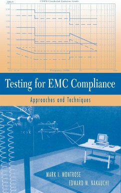
Written in an approachable, light-hearted tone, Testing for EMC Compliance is designed to help engineers and technicians who have had products fail regulatory EMI/EMC standards by identifying noise sources. This innovative book provides a wellspring of ideas and a step-by-step approach with helpful hints to track down problem areas or discover the mechanism that is creating and propagating undesired RF energy. Testing methods are provided to resolve problems as well as describing how to use EMI/EMC suppressing components. Finally, the book contains numerous "tricks of the trade" that make the trouble-shooting process more efficient.
The Keep It Simple (KISS) philosophy is the primary focus of this book. It is written in very simple language with minimal math, as a compilation of helpful EMI troubleshooting hints. Its light-hearted tone is at odds with the extreme seriousness of most engineering reference works that become boring after a few pages. This text tells engineers what to do and how to do it. Only a basic knowledge of math, electronics, and a basic understanding of EMI/EMC are necessary to understand the concepts and circuits described
Once EMC troubleshooting is demystified, readers learn there are quick and simple techniques to solve complicated problems a key aspect of this book. Simple and inexpensive methods to resolve EMI issues are discussed to help generate unique ideas and methods for developing additional diagnostic tools and measurement procedures. An appendix on how to build probes is included. It can be a fun activity, even humorous at times with bizarre techniques (i.e., the sticky finger probe)
Hinweis: Dieser Artikel kann nur an eine deutsche Lieferadresse ausgeliefert werden.
Produktdetails
- Produktdetails
- Verlag: Wiley & Sons
- 1. Auflage
- Seitenzahl: 480
- Erscheinungstermin: 8. April 2004
- Englisch
- Abmessung: 240mm x 161mm x 30mm
- Gewicht: 810g
- ISBN-13: 9780471433088
- ISBN-10: 047143308X
- Artikelnr.: 11742761
- Herstellerkennzeichnung
- Produktsicherheitsverantwortliche/r
- Europaallee 1
- 36244 Bad Hersfeld
- gpsr@libri.de
MARK I. MONTROSE is an expert in the fields of regulatory compliance, electromagnetic compatibility (EMC) and product safety. He has performed extensive research in the areas of EMC theory and signal integrity, and has written numerous papers on the subjects. Mr. Montrose is also a Senior Member of the IEEE and a member of the Board of Directors of both the IEEE EMC and Product Safety Engineering Society, as well as an active participant in local, national, and international activities of both Societies. He has published two prior books related to EMC and printed circuit boards. EDWARD M. NAKAUCHI has over thirty years of experience in analog, power, and digital design and has spent the majority of the past twenty years working in the EMI/EMC/EMP and ESD areas for military aerospace companies as well as commercial audio, computer, and medical organizations. He has written numerous technical papers and magazine articles, and presented seminars on various EMI/EMP/ESD topics. He has also taught courses on EMI/EMC through the University of California Irvine Extension program. He is a NARTE certified EMC/ESD engineer and an IEEE Senior Member.
Preface xiii
Acknowledgments xvii
1 Introduction 1
1.1 The Need to Comply 1
1.2 Definitions 3
1.3 Nature of Interference 5
1.4 Overview on Product Testing 6
1.4.1 Test Environment 6
1.4.2 Self-Compatibility 8
1.4.3 Validation of Measured Data 9
1.4.4 Problems during Emissions Testing 10
1.5 Time-Domain versus Frequency-Domain Analysis 12
1.6 EMC Testing Methodologies 14
1.6.1 Development Testing and Diagnostics 15
1.6.2 Compliance and Precompliance Testing 15
References 16
2 Electric, Magnetic, and Static Fields 17
2.1 Relationship between Electric and Magnetic Fields 17
2.2 Methods of Noise Coupling 22
2.2.1 Common-Impedance Coupling 24
2.2.2 Electromagnetic Field Coupling 25
2.2.3 Conductive Coupling 27
2.2.4 Radiated Coupling-Magnetic Field 27
2.2.5 Radiated Coupling-Electric Field 28
2.2.6 Radiated and Conducted Coupling Combined 31
2.3 Common-Mode Currents versus Differential-Mode Currents 32
2.3.1 Differential-Mode Currents 32
2.3.2 Common-Mode Currents 33
2.3.3 Example on Difference between Differential- and Common-Mode Currents
33
2.3.4 Radiation due to Differential-Mode Currents 36
2.3.5 Common-Mode Radiation 38
2.3.6 Conversion between Differential- and Common-Mode Energy 39
2.4 Static Fields 40
2.4.1 Electrostatic Discharge Waveforms 41
2.4.2 Triboelectric Series 41
2.4.3 Failure Modes From a Static Event 43
References 46
3 Instrumentation 47
3.1 Time-Domain Analyzer (Oscilloscope) 47
3.1.1 Oscilloscope Probes 52
3.2 Frequency-Domain Analyzers 53
3.2.1 Spectrum Analyzers 57
3.2.2 Receivers 64
3.3 Precompliance versus Compliance Analyzers 66
3.4 Correlation Analyzer 68
3.4.1 Characteristics of Cancellation System 70
3.4.2 Coherence Factor 71
References 75
4 Test Facilities 77
4.1 Open-Area Test Sites 78
4.1.1 Requirements for an OATS 78
4.1.2 Test Configuration-System, Power, and Cable Interconnects 85
4.1.3 Operating Conditions 87
4.1.4 Measurement Precautions 95
4.1.5 Alternate Test Sites 95
4.2 Chambers 96
4.2.1 Anechoic Chamber 97
4.2.2 Screen/Shield Rooms 104
4.2.3 Reverberation Chamber 107
4.3 Cells 109
4.3.1 TEM Cell 109
4.3.2 GTEM Cell 110
References 112
5 Probes, Antennas, and Support Equipment 113
5.1 Need for Probes, Antennas, and Support Equipment 113
5.2 Voltage Probes 115
5.3 Current Probes 116
5.3.1 Specifying a Current Probe 118
5.3.2 Limitations When Using Current Probes 122
5.4 LISN/AMN (AC Mains) 124
5.5 CDNs (Data and Signal Lines) 128
5.6 Absorbing Clamp 130
5.6.1 Test Setup and Measurement Procedure 132
5.7 Bulk Current Injection-Probe and Insertion Clamp 134
5.7.1 Choosing a BCI Probe 135
5.8 Basic Probe Types-Near Field and Closed Field 137
5.9 Sniffer Probes 140
5.9.1 Near-Field Probes 142
5.9.2 Commercial Probes 143
5.10 Differential-Mode Probes 143
5.11 Home-Made Probes 146
5.12 Alternate Troubleshooting Devices 147
5.13 Far-Field Antennas 150
5.13.1 Common Antennas Used for EMC Testing 153
References 156
6 Conducted Testing 157
6.1 Overview of Conducted Currents 157
6.1.1 Common- and Differential-Mode Currents on Wires and Cables 159
6.1.2 Coupling Paths for Conducted Emissions 161
6.1.3 Conducted Emissions Test Requirements 163
6.2 Performing Conducted Current Tests 163
6.2.1 Engineering Investigation in Laboratory or Engineer's Office 163
6.2.2 Test Environment 164
6.3 Conducted Emissions Testing (AC Power Mains) 164
6.3.1 Potential Problems during Conducted Emission Testing 166
6.3.2 In Situ Testing of Systems and Installations 167
6.4 Immunity/Susceptibility Tests 168
6.4.1 Electrical Fast Transient and Burst Testing 169
6.4.2 Surges 174
6.4.3 Conducted RF Current Immunity 181
6.4.3.1 Coupling Methods 181
6.4.3.2 Typical Conducted Immunity Test Setup and Equipment 184
6.4.3.3 Performing Typical Conducted Immunity Test 189
6.4.3.4 Diagnosis and Fixes 191
6.4.4 AC Mains Supply Dips, Dropouts, and Interruptions 192
6.4.4.1 AC Mains Supply Sags/Brownouts 195
6.4.4.2 Swell Testing 196
6.4.4.3 Three-Phase Equipment-Compliance Testing 198
6.4.4.4 Diagnosis and Fixes 198
6.4.5 Power Line Harmonics 199
6.4.5.1 How Harmonics Are Created and Related Concerns 200
6.4.5.2 Diagnosis and Fixes 211
6.4.6 Voltage Fluctuation and Flicker 211
6.4.6.1 Description of Short-Term Flicker 212
6.4.6.2 Instrumentation 213
References 215
7 Radiated Testing 217
7.1 Performing Radiated Tests 218
7.1.1 Engineering Investigation in Laboratory or Engineer's Office 220
7.1.2 Precompliance Testing 220
7.1.3 Performing Precompliance Analysis 223
7.1.4 Formal EMC Qualification Tests 224
7.1.5 Instrumentation Error 225
7.1.6 In Situ Testing of Systems and Installations 227
7.2 Immunity/Susceptibility Tests 228
7.2.1 Radiated Immunity 229
7.2.1.1 Modulation 231
7.2.1.2 Harmonic Issues 233
7.2.1.3 Monitoring of Immunity Field Level 234
7.2.2 Electrostatic Discharge 234
7.2.2.1 General Information 235
7.2.2.2 ESD Waveforms 235
7.2.2.3 Triboelectric Series 236
7.2.2.4 Typical Test Setup 237
7.2.2.5 EUT Performance Criteria 241
7.2.2.6 Diagnosis and Fixes 241
7.2.2.7 Concerns Related to Analyzing ESD Events 242
7.2.2.8 Alternative ESD Test Simulator 243
7.2.2.9 Other Uses for ESD Simulator 244
7.2.2.10 Sensing ESD Events within One's Environment 245
7.2.3 Power Frequency Magnetic Field Disturbance 245
7.2.3.1 General Conditions 246
7.2.3.2 EUT Performance Criteria 246
7.2.3.3 Typical Test Setup 247
7.2.3.4 Waveform Verification 249
7.2.3.5 Performing the Test 249
References 250
8 General Approaches to Troubleshooting 251
8.1 General System Testing and Troubleshooting 252
8.1.1 Emission Testing 253
8.1.2 Immunity Testing 255
8.1.3 In Situ Testing 256
8.2 Potential Problems During Testing and Troubleshooting 259
8.3 Testing and Troubleshooting Concerns 263
8.3.1 Systematic Approach for Emission Testing and Troubleshooting 264
8.3.2 Systematic Approach for Immunity Testing and Troubleshooting 266
8.3.3 Systematic Approach to Detecting and Locating Problems 267
8.3.4 Minimum Requirements for Performing EMC Tests 271
8.4 Repeatability of System Testing 272
8.5 Unexpected Problems after Production Has Begun 275
8.6 Creative Approaches to Troubleshooting (Case Studies) 276
References 277
9 On-Site Troubleshooting Techniques 279
9.1 Quick Fixes and Solutions 280
9.1.1 Conducted Solutions 281
9.1.2 Radiated Solutions 287
9.1.3 Crosstalk Solutions 291
9.2 Simplified Troubleshooting Techniques 292
9.2.1 The "Plain Wave and Standing Wave" Technique 293
9.2.2 The "Disabling-the-System" Technique 293
9.2.3 The "Cable Disconnection" Technique 294
9.2.4 The "Sticky Finger" Debugging Tool 295
9.2.5 The "Sharpen-Your-Pencil" Tool 296
9.2.6 The "Coolant Spray" Tool 297
9.2.7 The "Piece-of-Wire" Approach 298
9.2.8 The "Radio Control Race Car Diagnostic Sensor 298
9.2.9 The "Tin Can Wireless Antenna" for Signals above 1 GHz 300
9.3 Testing and Troubleshooting Using Probes 301
9.3.1 Using Probes for Immunity Testing and Troubleshooting 301
9.3.2 Differential Measurement of RF Currents on Cables and Interconnects
305
9.3.3 Switching Power Supply Effects on Common-Mode Conducted Noise 308
9.3.4 Discrete Component Diagnostic Tool 310
9.3.5 Tweezers Probe 311
9.3.6 Miniature High-Discrimination Probe 312
9.3.7 Using Current Probe as Substitute for Radiated Emission Testing 313
9.3.8 Enclosure Resonances and Shielding Effectiveness 315
9.4 Alternate Troubleshooting Techniques 316
9.4.1 Using Oscilloscope to Debug Signal Integrity Waveforms and Radiated
Emissions 316
9.4.2 Using Inexpensive Receivers for Emissions Testing 319
9.4.3 Using Amateur Radio Transmitter for Immunity Testing 321
9.4.4 Radiated Problem Masked as Conducted Emission Problem 322
9.4.5 Determining Whether Conducted Emission Noise is Differential Mode or
Common Mode 323
9.4.6 Another Use of EFT/B Generator 324
9.4.7 Signal Integrity Observations 325
9.5 System-Level Troubleshooting 326
9.5.1 Switching Power Supplies-Measuring Magnetic Field Coupling 326
9.5.2 Potential Problems When Using Ferrite Cores-Increase in Radiated
Emissions 328
9.5.3 Measuring Shielding Effectiveness of Materials and Enclosures 330
9.5.4 Measuring Effects of High-Frequency Noise Currents in Equipment 333
9.5.5 Measuring Noise Voltage across Seams in Enclosures 336
9.6 Ambient Cancellation or Suppression 339
9.7 Printed Circuit Board Diagnostic Scanners 341
References 345
Appendix A Building Probes 347
Appendix B Test Procedures 375
Glossary 435
Bibliography 447
Index 453
About the Authors 459
"...a very comprehensive book that should stand the test oftime...I recommend book to design and test engineers...asit is likely to be referred to again and again." ( IET.com )
"The authors have developed a logical approach to understandingtesting for EMC." ( IEEE EMC Society Newsletter , Summer2006)
"The authors have developed a logical approach to understandingtesting for EMC." ( IEEE EMC Society Newsletter , Summer2006)

