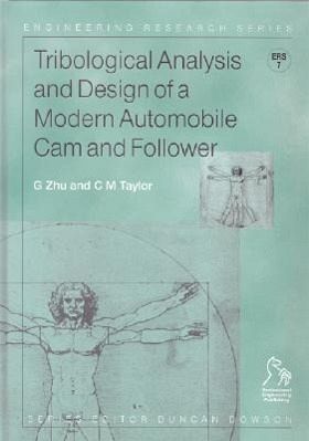
An Engineering Research Series title. This excellent and long awaited book is based upon extensive research carried out by the Institute of Tribology at the University of Leeds in the UK and the Ford Motor Company Ltd. It is concerned with both the theoretical and experimental study of the tribological performance of an automobile valve train, having an offset taper cam and a domed follower, incorporated with an hydraulic lash adjuster, with particular reference to the ZETA engine valve train. A sophisticated theoretical model has been developed that predicts the tribological performance of…mehr
An Engineering Research Series title. This excellent and long awaited book is based upon extensive research carried out by the Institute of Tribology at the University of Leeds in the UK and the Ford Motor Company Ltd. It is concerned with both the theoretical and experimental study of the tribological performance of an automobile valve train, having an offset taper cam and a domed follower, incorporated with an hydraulic lash adjuster, with particular reference to the ZETA engine valve train. A sophisticated theoretical model has been developed that predicts the tribological performance of the valve train, and also provides a useful tool for the consideration of the tribological design of valve trains. Additionally the model can estimate the instantaneous and average rotational frequency of the follower, and the performance of the hydraulic lash adjuster. In order to validate the theoretical model, the experimental measurements have been correlated with the theoretical predictions that simulate the test conditions of the valve train. The agreement between the measurements and the predictions show that the model is very reliable. This gives readers great confidence in using the model when dealing with novel and alternative designs of the valve train. COMPLETE CONTENTS: * Part One - Theoretical Formulation. Kinematics and dynamics of the cam and follower * Hydraulic lash adjuster * The maximum hertzian stresses * Asperity interactions * The oil film thickness * Friction and power loss of the valve train * The rotation of the follower * The overall solution procedure and input/output data * An example of the tribological analysis of a valve train. * Part Two - Experimental Study. Test apparatus and the instrumentation * Calibration of the instrumentation and commissioning tests * Test procedure * Data processing * Experimental results and discussions * Part Three - Correlation of theory and experiments. Experimental evidences * Theoretical predictions * Comparison of results and discussions * Overall conclusions.Hinweis: Dieser Artikel kann nur an eine deutsche Lieferadresse ausgeliefert werden.
Dr. Guangrui Zhu gained his PhD on engine valve train tribology at the University of Leeds, UK in 1988. He has worked in an industry-based R&D environment since then. He has published numerous journal and conference papers on journal bearings, trust bearings, mechanical seals, and valve trains. Professor Chris Taylor has researched in the area of lubrication for over 30 years, with engine tribology being a major theme in recent times.
Inhaltsangabe
Series Editor's Foreword xi Authors' Preface xiii Notation 1 Chapter 1 Introduction 5 Part I Theoretical Formulation Chapter 2 Kinematics and Dynamics of the Cam and Follower 11 2.1 Introduction 11 2.2 Kinematic analysis of a cam and domed flower pair 11 2.3 The load at the cam/follower interface 13 2.4 The solution procedure 15 2.5 References 15 Chapter 3 Hydraulic Lash Adjuster 17 3.1 Introduction 17 3.2 Check valve closed 17 3.2.1 The dynamics of the plunger 17 3.2.2 The governing equation of the displacement 19 3.2.3 Numerical analysis 20 3.3 Check valve open 21 3.3.1 The dynamics of the plunger 21 3.3.2 The governing equation of the displacement 23 3.3.3 Numerical analysis 24 3.4 The numerical solution procedure 24 Chapter 4 The Maximum Hertzian Stresses 25 4.1 Introduction 25 4.2 The contact geometry 25 4.3 The maximum Hertzian stress 27 4.4 The pressure distribution 27 4.5 The solution procedure 27 4.6 References 28 Chapter 5 Asperity Interactions 29 5.1 Introduction 29 5.2 The asperity contact force 29 5.3 The real area of contact 29 5.4 The asperity contact functions 30 5.5 The solution procedure 30 5.6 References 31 Chapter 6 The Oil Film Thickness 33 6.1 Introduction 33 6.2 The lubricant entraining velocity 33 6.3 The central and the minimum film thickness 35 6.4 The solution procedure 35 6.5 References 36 Chapter 7 Friction and Power Loss of the Valve Train 37 7.1 Introduction 37 7.2 The friction of the cam and follower interface 37 7.2.1 The friction due to shear of the lubricant 37 7.2.2 The friction due to asperity contact 38 7.3 The friction of the follower and bush interface 38 7.3.1 The tilting of the follower 39 7.3.2 The friction model 41 7.4 The friction of the valve and guide interface 42 7.5 The friction of the valve stem and valve seal interface 43 7.6 Power loss of the valve train 43 7.7 The solution procedure 44 7.8 References 44 Chapter 8 The Rotation of Follower 45 8.1 Introduction 45 8.2 The governing equation of the follower rotation 45 8.2.1 The Diving torque of the cam/follower interface 46 8.2.2 The resisting torque of the follower/bush interface 48 8.2.3 The resisting torque of the valve stem/plunger interface 49 8.3 The solution procedure 49 8.4 References 50 Chapter 9 The Overall Solution Procedure and Input and Output Data 51 9.1 Introduction 51 9.2 Input data 51 9.3 The kinematic analysis 51 9.4 The analysis of the hydraulic lash adjuster 51 9.5 Estimating the initial value of the follower rotational frequency 52 9.6 The tribological analysis of the valve train 54 9.7 The friction torque of the camshaft and average power loss 54 9.8 The output data 54 Chapter 10 An Example of the Tribological Analysis of a Valve Train 57 10.1 Introduction 57 10.2 Parameters of the intake valve train of the ZETEC engine 57 10.3 Results of the tribological analysis 59 10.4 A brief discussion of the results 59 10.5 References 60 Part II Experimental Study Chapter 11 Introduction to Experimental Study 87 11.1 Preamble 87 11.2 The background of the current experimental study 88 11.3 The aim of the experimental study 88 11.4 References 89 Chapter 12 Test Apparatus and the Instrumentation 91 12.1 Introduction 91 12.2 The hydraulic lash adjuster 91 12.3 The data acquisition system 91 12.4 Monitoring the follower rotation 93 12.5 Locating the cam position 94 12.6 Sampling the torque of the camshaft 94 12.7 References 95 Chapter 13 Calibration of the Instrumentation and Commissioning Tests 97 13.1 Introduction 97 13.2 Calibration of the instrumentation 97 13.2.1 The Calibration to the torque measurement system 97 13.2.2 The parasitic friction of the test apparatus 99 13.2.3 The calibration for monitoring the follower rotation 99 13.3 Commissioning tests 100 13.3.1 Improving the signal for the follower rotation100 13.3.2 Tests at different camshaft rotational frequencies 101 13.4 References 101 Chapter 14 The Test Procedure 103 14.1 Introduction 103 14.2 The running-in of the valve train 103 14.3 The loop test 103 14.4 The duration test 104 14.5 Tests at different bulk temperatures References 105 14.6 References 106 Chapter 15 The Data Processing 107 15.1 Introduction 107 15.2 The torque on the camshaft 107 15.3 The rotational frequency of the follower 107 15.4 The camshaft trigger signal 108 15.5 References 109 Chapter 16 Experimental Results and Discussions 111 16.1 Introduction 111 16.2 Experimental variables and the test condition 111 16.3 Experimental results and discussions 112 16.3.1 The friction torque and power loss of the valve train 112 16.3.2 The rotational frequency of the follower 113 16.3.3 Inspection of the cam and the follower 121 16.4 Conclusions 122 16.5 References 124 Part III Correlation Of Theory And Experiments Chapter 17 Introduction to Correlation of Theory and Experiments 127 Chapter 18 The Experimental Evidence 129 Chapter 19 The Theoretical Predictions 131 19.1 Introduction 131 19.2 Kinematics and dynamics 131 19.3 The cam/follower interface 131 19.4 The follower/bore interface 132 19.5 The hydraulic lash adjuster 133 19.6 The rotation of the follower 133 19.7 References 133 Chapter 20 The Comparison of Results and Discussions 135 20.1 Introduction 135 20.2 The input data of the model simulating the test conditions 135 20.3 The results of comparison and discussions 137 20.3.1 The average friction torque 137 20.3.2 The instantaneous torque on the camshaft 140 20.3.3 The instantaneous friction torque on the camshaft 140 20.3.4 The average follower rotational frequency 145 20.3.5 The instantaneous follower rotational frequency 146 20.4 Conclusions 149 20.5 References 149 Chapter 21 Overall Conclusions 151 Index 153
Es gelten unsere Allgemeinen Geschäftsbedingungen: www.buecher.de/agb
Impressum
www.buecher.de ist ein Internetauftritt der buecher.de internetstores GmbH
Geschäftsführung: Monica Sawhney | Roland Kölbl | Günter Hilger
Sitz der Gesellschaft: Batheyer Straße 115 - 117, 58099 Hagen
Postanschrift: Bürgermeister-Wegele-Str. 12, 86167 Augsburg
Amtsgericht Hagen HRB 13257
Steuernummer: 321/5800/1497