Franco Maloberti
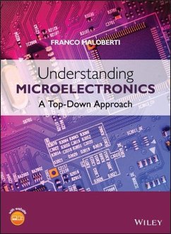
Understanding Microelectronics
Franco Maloberti
Understanding Microelectronics
- Gebundenes Buch
- Merkliste
- Auf die Merkliste
- Bewerten Bewerten
- Teilen
- Produkt teilen
- Produkterinnerung
- Produkterinnerung
The microelectronics evolution has given rise to many modern benefits but has also changed design methods and attitudes to learning. Technology advancements shifted focus from simple circuits to complex systems with major attention to high-level descriptions. The design methods moved from a bottom-up to a top-down approach.
For today's students, the most beneficial approach to learning is this top-down method that demonstrates a global view of electronics before going into specifics. Franco Maloberti uses this approach to explain the fundamentals of electronics, such as processing…mehr
Andere Kunden interessierten sich auch für
![Asynchronous Circuit Design Asynchronous Circuit Design]() Chris J. MyersAsynchronous Circuit Design211,99 €
Chris J. MyersAsynchronous Circuit Design211,99 €![Mosfet Models for Spice Simulation Mosfet Models for Spice Simulation]() William LiuMosfet Models for Spice Simulation265,99 €
William LiuMosfet Models for Spice Simulation265,99 €![VLSI Circuit Design Methodology VLSI Circuit Design Methodology]() Liming XiuVLSI Circuit Design Methodology121,99 €
Liming XiuVLSI Circuit Design Methodology121,99 €![Introduction to Microfabrication Introduction to Microfabrication]() Sami FranssilaIntroduction to Microfabrication82,99 €
Sami FranssilaIntroduction to Microfabrication82,99 €![Computer System Design Computer System Design]() Michael J. FlynnComputer System Design102,99 €
Michael J. FlynnComputer System Design102,99 €![Phase Lock Loops and Frequency Synthesis Phase Lock Loops and Frequency Synthesis]() Vinceslav F. KroupaPhase Lock Loops and Frequency Synthesis219,99 €
Vinceslav F. KroupaPhase Lock Loops and Frequency Synthesis219,99 €![Device Modeling for Analog and RF CMOS Circuit Design Device Modeling for Analog and RF CMOS Circuit Design]() Trond YtterdalDevice Modeling for Analog and RF CMOS Circuit Design208,99 €
Trond YtterdalDevice Modeling for Analog and RF CMOS Circuit Design208,99 €-
-
-
The microelectronics evolution has given rise to many modern benefits but has also changed design methods and attitudes to learning. Technology advancements shifted focus from simple circuits to complex systems with major attention to high-level descriptions. The design methods moved from a bottom-up to a top-down approach.
For today's students, the most beneficial approach to learning is this top-down method that demonstrates a global view of electronics before going into specifics. Franco Maloberti uses this approach to explain the fundamentals of electronics, such as processing functions, signals and their properties. Here he presents a helpful balance of theory, examples, and verification of results, while keeping mathematics and signal processing theory to a minimum.
Key features:
Presents a new learning approach that will greatly improve students' ability to retain key concepts in electronics studies
Match the evolution of Computer Aided Design (CAD) which focuses increasingly on high-level design
Covers sub-functions as well as basic circuits and basic components
Provides real-world examples to inspire a thorough understanding of global issues, before going into the detail of components and devices
Discusses power conversion and management; an important area that is missing in other books on the subject
End-of-chapter problems and self-training sections support the reader in exploring systems and understanding them at increasing levels of complexity
A supporting website presents the interactive student lab, ElvisLAB, where students can conduct virtual experiments on circuits together with PowerPoint slides for lecturers.
Inside this book you will find a complete explanation of electronics that can be applied across a range of disciplines including electrical engineering and physics. This comprehensive introduction will be of benefit to students studying electronics, as well as their lecturers and professors. Postgraduate engineers, those in vocational training, and design and application engineers will also find this book useful.
Hinweis: Dieser Artikel kann nur an eine deutsche Lieferadresse ausgeliefert werden.
Produktdetails
- Produktdetails
- Verlag: Wiley & Sons
- Artikelnr. des Verlages: 14574555000
- 1. Auflage
- Seitenzahl: 696
- Erscheinungstermin: 12. Dezember 2011
- Englisch
- Abmessung: 257mm x 197mm x 35mm
- Gewicht: 1493g
- ISBN-13: 9780470745557
- ISBN-10: 047074555X
- Artikelnr.: 33236431
- Herstellerkennzeichnung
- Produktsicherheitsverantwortliche/r
- Europaallee 1
- 36244 Bad Hersfeld
- gpsr@libri.de
Professor Franco Maloberti, University of Pavia, Italy Franco Maloberti is currently Professor of Microelectronics and Head of the Micro Integrated? Systems Group at the University of Pavia. His specialized subjects are in the design, analysis and characterization of integrated circuits and analog digital applications, mainly in the areas of switched-capacitor circuits, data converters, interfaces for telecommunication and sensor systems, and CAD for analog and mixed A/D design. He has written four books and over 370 papers on these topics, and holds 27 patents. Recipient of the XII Pedriali Prize for his technical and scientific contributions to national industrial production, Dr Maloberti was also the co-recipient of the 1996 Institute of Electrical Engineers Fleming Premium, the best Paper award, ESSCIRC-2007, and the best paper award, IEEJ Analog Workshop-2007. He received the 1999 IEEE CAS Society Meritorious Service Award, the 2000 CAS Society Golden Jubilee Medal, and the 2000 IEEE Millennium Medal. Dr Maloberti was the President of the IEEE Sensor Council from 2002 to 2003, and Vice-President, Region 8, of the IEEE CAS Society from 1995 to 1997, also an Associate Editor of IEEE TCAS-II. He is an IEEE Fellow and is presently serving as VP Publications of the IEEE CAS Society.
Preface xvii
List of Abbreviations xxi
1 Overview, Goals and Strategy 1
1.1 Good Morning 1
1.2 Planning the Trip 4
1.3 Electronic Systems 5
1.3.1 Meeting a System 8
1.4 Transducers 11
1.4.1 Sensors 11
1.4.2 Actuators 14
1.5 What is the Role of the Computer? 16
1.6 Goal and Learning Strategies 19
1.6.1 Teamwork Attitude 20
1.6.2 Creativity and Execution 20
1.6.3 Use of Simulation Tools 21
1.7 Self Training, Examples and Simulations 21
1.7.1 Role of Examples and Computer Simulations 22
1.8 Business Issues, Complexity and CAD Tools 23
1.8.1 CAD Tools 23
1.8.2 Analog Simulator 24
1.8.3 Device and Macro-block Models 25
1.8.4 Digital Simulation 26
1.9 ELectronic VIrtual Student Lab (ElvisLab) 27
Problems 29
2 Signals 31
2.1 Introduction 31
2.2 Types of Signals 35
2.3 Time and Frequency Domains 45
2.4 Continuous-time and Discrete-time Signals 51
2.4.1 The Sampling Theorem 55
2.5 Using Sampled-Data Signals 57
2.5.1 The z-transform 58
2.6 Discrete-amplitude Signals 59
2.6.1 Quantized Signal Coding 64
2.7 Signals Representation 65
2.7.1 The Decibel 67
2.8 DFT and FFT 69
2.9 Windowing 70
2.10 Good and Bad Signals 75
2.10.1 Offset 76
2.10.2 Interference 77
2.10.3 Harmonic Distortion 78
2.10.4 Noise 82
2.11 THD, SNR, SNDR, Dynamic Range 86
Problems 89
Additional Computer Examples 92
3 Electronic Systems 95
3.1 Introduction 95
3.2 Electronics for Entertainment 96
3.2.1 Electronic Toys 96
3.2.2 Video Game and Game Console 100
3.2.3 Personal Media Player 101
3.3 Systems for Communication 103
3.3.1 Wired Communication Systems 103
3.3.2 Wireless: Voice, Video and Data 104
3.3.3 RFID 107
3.4 Computation and Processing 108
3.4.1 Microprocessor 110
3.4.2 Digital Signal Processor 111
3.4.3 Data Storage 112
3.5 Measure, Safety, and Control 114
3.5.1 The Weather Station 115
3.5.2 Data Fusion 116
3.5.3 Systems for Automobile Control 119
3.5.4 Noise-canceling Headphones 120
3.6 System Partitioning 122
3.7 System Testing 124
Problems 125
Additional Computer Examples 126
4 Signal Processing 127
4.1 What is Signal Processing? 127
4.2 Linear and Non-linear Processing 130
4.3 Analog and Digital Processing 135
4.3.1 Timing for Signal Processing 138
4.4 Response of Linear Systems 141
4.4.1 Time Response of Linear Systems 141
4.4.2 Frequency Response of Linear Systems 144
4.4.3 Transfer Function 147
4.5 Bode Diagram 151
4.5.1 Amplitude Bode Diagram 151
4.5.2 Phase Bode Diagram 155
4.6 Filters 158
4.6.1 Analog Design and Sensitivity 162
4.6.2 Sampled-data Analog and Digital Design 167
4.7 Non-linear Processing 169
Problems 175
Additional Computer Examples 179
5 Circuits for Systems 181
5.1 Introduction 181
5.2 Processing with Electronic Circuits 183
5.2.1 Electronic Interfaces 184
5.2.2 Driving Capability 188
5.2.3 Electrostatic Discharge Protection 191
5.2.4 DC and AC Coupling 193
5.2.5 Ground and Ground for Signal 197
5.2.6 Single-ended and Differential Circuits 198
5.3 Inside Analog Electronic Blocks 200
5.3.1 Simple Continuous-time Filters 201
5.3.2 Two-Pole Filters 205
5.4 Continuous-time Linear Basic Functions 205
5.4.1 Addition of Signals 206
5.4.2 The Virtual Ground Concept 209
5.4.3 Multiplication by a Constant 212
5.4.4 Integration and Derivative 214
5.5 Continuous-time Non-linear Basic Functions 221
5.5.1 Threshold Detection 222
5.5.2 Analog Multiplier 223
5.6 Analog Discrete-time Basic Operations 225
5.7 Limits in Real Analog Circuits 227
5.8 Circuits for Digital Design 229
5.8.1 Symbols of Digital Blocks 230
5.8.2 Implementation of Digital Functions 233
Problems 234
6 Analog Processing Blocks 239
6.1 Introduction 239
6.2 Choosing the Part 241
6.3 Operational Amplifier 242
6.3.1 Ideal Operation 242
6.4 Op-Amp Description 244
6.4.1 General Description 244
6.4.2 Absolute Maximum Ratings and Operating Rating 244
6.4.3 Electrical Characteristics 245
6.4.4 Packaging and Board Assembly 254
6.4.5 Small-signal Equivalent Circuit 255
6.5 Use of Operational Amplifiers 257
6.5.1 Inverting Amplifier 257
6.5.2 Non-inverting Amplifier 261
6.5.3 Superposing Inverting and Non-inverting Amplification 262
6.5.4 Weighted Addition of Signals (with Inversion) 264
6.5.5 Unity Gain Buffer 265
6.5.6 Integration and Derivative 266
6.5.7 Generalized Amplifier 268
6.6 Operation with Real Op-amps 269
6.6.1 Input Offset 269
6.6.2 Finite Gain 270
6.6.3 Non-ideal Input and Output Impedances 271
6.6.4 Finite Bandwidth 276
6.6.5 Slew-rate Output Clipping and Non-linear Gain 277
6.7 Operational Transconductance Amplifier 280
6.7.1 Use of the OTA 280
6.8 Comparator 284
6.8.1 Comparator Data Sheet 286
6.8.2 Clocked Comparator 289
Problems 289
7 Data Converters 293
7.1 Introduction 293
7.2 Types and Specifications 295
7.2.1 General Features 295
7.2.2 Electrical Static Specifications 296
7.2.3 Electrical Dynamic Specifications 299
7.2.4 Digital and Switching Data 302
7.3 Filters for Data Conversion 303
7.3.1 Anti-aliasing and Reconstruction Filters 303
7.3.2 Oversampling and Digital Filters 305
7.4 Nyquist-rate DAC 306
7.4.1 Resistor-based Architectures 306
7.4.2 Capacitance-based Architectures 312
7.4.3 Parasitic Insensitivity 314
7.4.4 Hybrid Resistive-capacitive Architectures 316
7.4.5 Current-based Architectures 317
7.5 Nyquist-rate ADC 321
7.5.1 Flash Converter 322
7.5.2 Two-step Flash 324
7.5.3 Pipeline Converters 327
7.5.4 Slow Converters 328
7.6 Oversampled Converter 332
7.6.1 Quantization Error and Quantization Noise 332
7.6.2 Benefit of the Noise View 336
7.6.3 Sigma-Delta Modulators 337
7.7 Decimation and Interpolation 342
Problems 344
8 Digital Processing Circuits 347
8.1 Introduction 347
8.2 Digital Waveforms 348
8.2.1 Data Transfer and Data Communication 350
8.2.2 Propagation Delay 354
8.2.3 Asynchronous and Synchronous Operation 355
8.3 Combinational and Sequential Circuits 356
8.3.1 Combinational Circuits 356
8.3.2 Sequential Circuits 358
8.4 Digital Architectures with Memories 360
8.5 Logic and Arithmetic Functions 362
8.5.1 Adder and Subtracter 362
8.5.2 Multiplier 365
8.5.3 Registers and Counters 371
8.6 Circuit Design Styles 377
8.6.1 Complex Programmable Logic Devices (CPLDs) and FPGAs 378
8.7 Memory Circuits 381
8.7.1 Random-access Memory Organization and Speed 382
8.7.2 Types of Memories 384
8.7.3 Circuits for Memories 386
Problems 391
9 Basic Electronic Devices 393
9.1 Introduction 393
9.2 The Diode 395
9.2.1 Equivalent Circuit 398
9.2.2 Parasitic Junction Capacitance 400
9.2.3 Zener and Avalanche Breakdown 402
9.2.4 Doping and p-n Junction 403
9.2.5 Diode in Simple Circuits 407
9.3 The MOS Transistor 411
9.3.1 MOS Physical Structure 412
9.3.2 Voltage-current Relationship 414
9.3.3 Approximating the I-V Equation 416
9.3.4 Parasitic Effects 417
9.3.5 Equivalent Circuit 419
9.4 MOS Transistor in Simple Circuits 421
9.5 The Bipolar Junction Transistor (BJT) 423
9.5.1 The BJT Physical Structure 426
9.5.2 BJT Voltage-current Relationships 427
9.5.3 Bipolar Transistor Model and Parameters 431
9.5.4 Darlington Configuration 433
9.5.5 Small-signal Equivalent Circuit of the Bipolar Transistor 434
9.6 Bipolar Transistor in Simple Circuits 435
9.7 The Junction Field-effect Transistor (JFET) 439
9.8 Transistors for Power Management 441
Problems 443
10 Analog Building Cells 445
10.1 Introduction 445
10.2 Use of Small-signal Equivalent Circuits 446
10.3 Inverting Voltage Amplifier 447
10.4 MOS Inverter with Resistive Load 451
10.4.1 Small-signal Analysis of the CMOS Inverter 452
10.5 CMOS Inverter with Active Load 454
10.5.1 CMOS Inverter with Active Load: Small-signal Analysis 456
10.6 Inverting Amplifier with Bipolar Transistors 459
10.6.1 Small-signal Analysis of BJT Inverters 462
10.7 Source and Emitter Follower 471
10.7.1 Small-signal Equivalent Circuit of Source and Emitter Follower 473
10.7.2 Small-signal Input and Output Resistance 474
10.8 Cascode with Active Load 477
10.8.1 Equivalent Resistances 480
10.8.2 Cascode with Cascode Load 482
10.9 Differential Pair 483
10.10 Current Mirror 487
10.10.1 Equivalent Circuit 488
10.10.2 Current Mirror with High Output Resistance 489
10.10.3 Differential to Single-ended Converter 490
10.11 Reference Generators 492
Problems 493
11 Digital Building Cells 495
11.1 Introduction 495
11.2 Logic Gates 496
11.2.1 Gate Specifications 497
11.3 Boolean Algebra and Logic Combinations 499
11.4 Combinational Logic Circuits 504
11.4.1 Exclusive-OR and Exclusive-NOR 505
11.4.2 Half-adder and Full-adder 507
11.4.3 Logic Comparators 509
11.4.4 Decoders 511
11.4.5 Parity Generator and Parity Checker 513
11.5 Sequential Logic Circuits 514
11.5.1 Latch 514
11.5.2 Gated Latch 516
11.5.3 Edge-triggered Flip-flop 517
11.5.4 Master-slave Flip-flop 519
11.6 Flip-flop Specifications 520
11.7 Transistor Schemes of Logic Cells 522
11.7.1 CMOS Inverter 522
11.7.2 Dynamic Response of CMOS Inverters 526
11.7.3 Power Consumption 529
11.7.4 NOR and NAND 530
11.7.5 Pass-gate Logic 532
11.7.6 Tri-state Gates 534
11.7.7 Dynamic Logic Circuits 535
Problems 536
12 Feedback 539
12.1 Introduction 539
12.2 General Configuration 540
12.2.1 Linear Feedback Systems 541
12.3 Properties of Negative Feedback 543
12.3.1 Gain Sensitivity 545
12.3.2 Bandwidth Improvement 545
12.3.3 Reducing Distortion 547
12.3.4 Noise Behavior 549
12.4 Types of Feedback 551
12.4.1 Real Input and Output Ports 553
12.4.2 Input and Output Resistances 555
12.5 Stability 559
12.5.1 Frequency Response of Feedback Circuits 559
12.5.2 Gain and Phase Margins 562
12.5.3 Compensation of Operational Amplifiers 563
12.6 Feedback Networks 566
Problems 568
13 Power Conversion and Power Management 571
13.1 Introduction 571
13.2 Voltage Rectifiers 572
13.2.1 Half-wave Rectifier 573
13.2.2 Full-wave Rectifier 577
13.3 Voltage Regulators 581
13.3.1 Zener Regulator 581
13.3.2 Series Linear Regulator 583
13.3.3 Series Linear Regulator with Adjustable Voltage 588
13.3.4 Supply of Active Blocks and Drop-out Voltage 590
13.3.5 Low Drop-out (LDO) Voltage Regulator 591
13.3.6 Protection Circuits 593
13.4 Switched Capacitor Regulator 595
13.4.1 Power Consumed by SC Regulators 597
13.4.2 Generation of Negative Voltages 599
13.4.3 Voltage Ripple 600
13.5 Charge Pump 601
13.6 Switching Regulators 604
13.6.1 Buck Converter 605
13.6.2 Boost Converter 607
13.6.3 Buck-boost Converter 610
13.6.4 Loop Control and Switches 611
13.6.5 Efficiency of Switching Regulator 613
13.7 Power Management 615
13.7.1 Rechargeable Batteries 615
13.7.2 Power Harvesting 618
13.7.3 Power Management Techniques 620
Problems 622
14 Signal Generation and Signal Measurement 623
14.1 Introduction 623
14.2 Generation of Simple Waveforms 624
14.3 Oscillators 627
14.3.1 Wien-bridge Oscillator 629
14.3.2 Phase-shift Oscillator 630
14.3.3 Ring Oscillator 631
14.3.4 Tank and Harmonic Oscillator 634
14.3.5 Digitally Controlled and Voltage-controlled Oscillator (VCO) 636
14.3.6 Quartz Oscillator 638
14.3.7 Phase Noise and Jitter 640
14.3.8 Phase-locked Oscillator 642
14.4 DAC-based Signal Generator 647
14.5 Signal Measurement 649
14.5.1 Multimeter 651
14.5.2 Oscilloscope 652
14.5.3 Logic Analyzer 655
14.6 Spectrum Analyzer 657
Problems 658
Index 661

