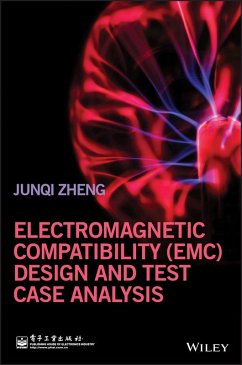
Electromagnetic Compatibility (EMC) Design and Test Case Analysis (eBook, ePUB)


Alle Infos zum eBook verschenken

Electromagnetic Compatibility (EMC) Design and Test Case Analysis (eBook, ePUB)
- Format: ePub
- Merkliste
- Auf die Merkliste
- Bewerten Bewerten
- Teilen
- Produkt teilen
- Produkterinnerung
- Produkterinnerung

Hier können Sie sich einloggen

Bitte loggen Sie sich zunächst in Ihr Kundenkonto ein oder registrieren Sie sich bei bücher.de, um das eBook-Abo tolino select nutzen zu können.
A practical introduction to techniques for the design of electronic products from the Electromagnetic compatibility (EMC) perspective * Introduces techniques for the design of electronic products from the EMC aspects * Covers normalized EMC requirements and design principles to assure product compatibility * Describes the main topics for the control of electromagnetic interferences and recommends design improvements to meet international standards requirements (FCC, EU EMC directive, Radio acts, etc.) * Well organized in a logical sequence which starts from basic knowledge and continues…mehr
- Geräte: eReader
- mit Kopierschutz
- eBook Hilfe
- Größe: 73.5MB
![Electromagnetic Compatibility (EMC) Design and Test Case Analysis (eBook, PDF) Electromagnetic Compatibility (EMC) Design and Test Case Analysis (eBook, PDF)]() Junqi ZhengElectromagnetic Compatibility (EMC) Design and Test Case Analysis (eBook, PDF)123,99 €
Junqi ZhengElectromagnetic Compatibility (EMC) Design and Test Case Analysis (eBook, PDF)123,99 €![Foundations of Electromagnetic Compatibility (eBook, ePUB) Foundations of Electromagnetic Compatibility (eBook, ePUB)]() Bogdan AdamczykFoundations of Electromagnetic Compatibility (eBook, ePUB)117,99 €
Bogdan AdamczykFoundations of Electromagnetic Compatibility (eBook, ePUB)117,99 €![Handbook of Aerospace Electromagnetic Compatibility (eBook, ePUB) Handbook of Aerospace Electromagnetic Compatibility (eBook, ePUB)]() Handbook of Aerospace Electromagnetic Compatibility (eBook, ePUB)130,99 €
Handbook of Aerospace Electromagnetic Compatibility (eBook, ePUB)130,99 €![Introduction to Microfabrication (eBook, ePUB) Introduction to Microfabrication (eBook, ePUB)]() Sami FranssilaIntroduction to Microfabrication (eBook, ePUB)67,99 €
Sami FranssilaIntroduction to Microfabrication (eBook, ePUB)67,99 €![Transmission Lines in Digital Systems for EMC Practitioners (eBook, ePUB) Transmission Lines in Digital Systems for EMC Practitioners (eBook, ePUB)]() Clayton R. PaulTransmission Lines in Digital Systems for EMC Practitioners (eBook, ePUB)86,99 €
Clayton R. PaulTransmission Lines in Digital Systems for EMC Practitioners (eBook, ePUB)86,99 €![Introduction to Electromagnetic Compatibility (eBook, ePUB) Introduction to Electromagnetic Compatibility (eBook, ePUB)]() Clayton R. PaulIntroduction to Electromagnetic Compatibility (eBook, ePUB)103,99 €
Clayton R. PaulIntroduction to Electromagnetic Compatibility (eBook, ePUB)103,99 €![Advances in Time-Domain Computational Electromagnetic Methods (eBook, ePUB) Advances in Time-Domain Computational Electromagnetic Methods (eBook, ePUB)]() Advances in Time-Domain Computational Electromagnetic Methods (eBook, ePUB)111,99 €
Advances in Time-Domain Computational Electromagnetic Methods (eBook, ePUB)111,99 €-
-
-
Dieser Download kann aus rechtlichen Gründen nur mit Rechnungsadresse in A, B, BG, CY, CZ, D, DK, EW, E, FIN, F, GR, HR, H, IRL, I, LT, L, LR, M, NL, PL, P, R, S, SLO, SK ausgeliefert werden.
- Produktdetails
- Verlag: John Wiley & Sons
- Seitenzahl: 496
- Erscheinungstermin: 11. Februar 2019
- Englisch
- ISBN-13: 9781118956830
- Artikelnr.: 55282044
- Verlag: John Wiley & Sons
- Seitenzahl: 496
- Erscheinungstermin: 11. Februar 2019
- Englisch
- ISBN-13: 9781118956830
- Artikelnr.: 55282044
- Herstellerkennzeichnung Die Herstellerinformationen sind derzeit nicht verfügbar.
Exordium xv
Introduction xix
1 The EMC Basic Knowledge and the Essence of the EMC Test 1
1.1 What Is EMC? 1
1.2 Conduction, Radiation, and Transient 2
1.3 Theoretical Basis 4
1.3.1 Time Domain and Frequency Domain 4
1.3.2 The Concept of the Unit for Electromagnetic Disturbance, dB 5
1.3.3 The True Meaning of Decibel 6
1.3.4 Electric Field, Magnetic Field, and Antennas 9
1.3.5 Resonance of the RLC Circuit 17
1.4 Common Mode and Differential Mode in the EMC Domain 21
1.5 Essence of the EMC Test 23
1.5.1 Essence of the Radiated Emission Test 23
1.5.2 Essence of the Conducted Emission Test 25
1.5.3 Essence of the ESD Immunity Test 29
1.5.4 Essence of the Radiated Immunity Test 30
1.5.5 Essence of the Common-Mode Conducted Immunity Test 32
1.5.6 Essence of the Differential-Mode Conducted Immunity Test 34
1.5.7 Differential-Mode and Common-Mode Hybrid Conducted Immunity Test 35
2 Architecture, Shielding, and Grounding Versus EMC of the Product 37
2.1 Introduction 37
2.1.1 Architecture Versus EMC of the Product 37
2.1.2 Shielding Versus EMC of the Product 38
2.1.3 Grounding Versus EMC of the Product 40
2.2 Analyses of Related Cases 41
2.2.1 Case 1: The Conducted Disturbance and the Grounding 41
2.2.2 Case 2: The Ground Loop During the Conducted Emission Test 46
2.2.3 Case 3: Where the Radiated Emission Outside the Shield Comes From 49
2.2.4 Case 4: The "Floating" Metal and the Radiation 52
2.2.5 Case 5: Radiated Emission Caused by the Bolt Extended Outside the Shield 55
2.2.6 Case 6: The Compression Amount of the Shield and Its Shielding Effectiveness 59
2.2.7 Case 7: The EMI Suppression Effectiveness of the Shielding Layer Between the Transformer's Primary Winding and Secondary Winding in the Switching-Mode Power Supply 62
2.2.8 Case 8: Bad Contact of the Metallic Casing and System Reset 68
2.2.9 Case 9: ESD Discharge and the Screw 70
2.2.10 Case 10: Heatsink Also Affects the ESD Immunity 71
2.2.11 Case 11: How Grounding Benefits EMC Performance 72
2.2.12 Case 12: The Heatsink Shape Affects Conducted Emissions from the Power Ports 76
2.2.13 Case 13: The Metallic Casing Oppositely Causes the EMI Test Failed 82
2.2.14 Case 14: Whether Directly Connecting the PCB Reference Ground to the Metallic Casing Will Lead to ESD 88
2.2.15 Case 15: How to Interconnect the Digital Ground and the Analog Ground in the Digital-Analog Mixed Devices 94
3 EMC Issues with Cables, Connectors, and Interface Circuits 101
3.1 Introduction 101
3.1.1 Cable Is the Weakest Link in the System 101
3.1.2 The Interface Circuit Provides Solutions to the Cable Radiation Problem 102
3.1.3 Connectors Are the Path Between the Interface Circuit and the Cable 103
3.1.4 The Interconnection between the PCBs Is the Weakest Link of the Product EMC 104
3.2 Analyses of Related Cases 107
3.2.1 Case 16: The Excessive Radiation Caused by the Cabling 107
3.2.2 Case 17: Impact from the Pigtail of the Shielded Cable 110
3.2.3 Case 18: The Radiated Emission from the Grounding Cable 113
3.2.4 Case 19: Is the Shielded Cable Clearly Better than the Unshielded Cable? 117
3.2.5 Case 20: Impacts on ESD Immunity of the Plastic Shell Connectors and the Metallic Shell Connector 124
3.2.6 Case 21: The Selection of the Plastic Shell Connector and the ESD Immunity 126
3.2.7 Case 22: Wh
