
Alle Infos zum eBook verschenken

- Format: ePub
- Merkliste
- Auf die Merkliste
- Bewerten Bewerten
- Teilen
- Produkt teilen
- Produkterinnerung
- Produkterinnerung

Hier können Sie sich einloggen

Bitte loggen Sie sich zunächst in Ihr Kundenkonto ein oder registrieren Sie sich bei bücher.de, um das eBook-Abo tolino select nutzen zu können.
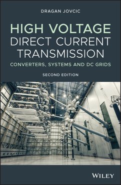
Presents the latest developments in switchgear and DC/DC converters for DC grids, and includes substantially expanded material on MMC HVDC This newly updated edition covers all HVDC transmission technologies including Line Commutated Converter (LCC) HVDC; Voltage Source Converter (VSC) HVDC, and the latest VSC HVDC based on Modular Multilevel Converters (MMC), as well as the principles of building DC transmission grids. Featuring new material throughout, High Voltage Direct Current Transmission: Converters, Systems and DC Grids, 2nd Edition offers several new chapters/sections including one on…mehr
- Geräte: eReader
- mit Kopierschutz
- eBook Hilfe
- Größe: 59.2MB
![Extruded Cables for High-Voltage Direct-Current Transmission (eBook, ePUB) Extruded Cables for High-Voltage Direct-Current Transmission (eBook, ePUB)]() Giovanni MazzantiExtruded Cables for High-Voltage Direct-Current Transmission (eBook, ePUB)116,99 €
Giovanni MazzantiExtruded Cables for High-Voltage Direct-Current Transmission (eBook, ePUB)116,99 €![Alternative Liquid Dielectrics for High Voltage Transformer Insulation Systems (eBook, ePUB) Alternative Liquid Dielectrics for High Voltage Transformer Insulation Systems (eBook, ePUB)]() Alternative Liquid Dielectrics for High Voltage Transformer Insulation Systems (eBook, ePUB)118,99 €
Alternative Liquid Dielectrics for High Voltage Transformer Insulation Systems (eBook, ePUB)118,99 €![Multi-terminal High-voltage Converter (eBook, ePUB) Multi-terminal High-voltage Converter (eBook, ePUB)]() Bo ZhangMulti-terminal High-voltage Converter (eBook, ePUB)111,99 €
Bo ZhangMulti-terminal High-voltage Converter (eBook, ePUB)111,99 €![Multi-terminal High-voltage Converter (eBook, ePUB) Multi-terminal High-voltage Converter (eBook, ePUB)]() Bo ZhangMulti-terminal High-voltage Converter (eBook, ePUB)111,99 €
Bo ZhangMulti-terminal High-voltage Converter (eBook, ePUB)111,99 €![Power Grid Resilience against Natural Disasters (eBook, ePUB) Power Grid Resilience against Natural Disasters (eBook, ePUB)]() Shunbo LeiPower Grid Resilience against Natural Disasters (eBook, ePUB)111,99 €
Shunbo LeiPower Grid Resilience against Natural Disasters (eBook, ePUB)111,99 €![Multi-terminal Direct-Current Grids (eBook, ePUB) Multi-terminal Direct-Current Grids (eBook, ePUB)]() Nilanjan ChaudhuriMulti-terminal Direct-Current Grids (eBook, ePUB)123,99 €
Nilanjan ChaudhuriMulti-terminal Direct-Current Grids (eBook, ePUB)123,99 €![Voltage-Enhanced Processing of Biomass and Biochar (eBook, ePUB) Voltage-Enhanced Processing of Biomass and Biochar (eBook, ePUB)]() Gerardo DiazVoltage-Enhanced Processing of Biomass and Biochar (eBook, ePUB)102,99 €
Gerardo DiazVoltage-Enhanced Processing of Biomass and Biochar (eBook, ePUB)102,99 €-
-
-
Dieser Download kann aus rechtlichen Gründen nur mit Rechnungsadresse in A, B, BG, CY, CZ, D, DK, EW, E, FIN, F, GR, HR, H, IRL, I, LT, L, LR, M, NL, PL, P, R, S, SLO, SK ausgeliefert werden.
- Produktdetails
- Verlag: John Wiley & Sons
- Seitenzahl: 560
- Erscheinungstermin: 1. Juli 2019
- Englisch
- ISBN-13: 9781119566618
- Artikelnr.: 58582072
- Verlag: John Wiley & Sons
- Seitenzahl: 560
- Erscheinungstermin: 1. Juli 2019
- Englisch
- ISBN-13: 9781119566618
- Artikelnr.: 58582072
- Herstellerkennzeichnung Die Herstellerinformationen sind derzeit nicht verfügbar.
Section 68 7.7.2 Controller Model 69 7.7.3 Complete DC System Model 69 7.8 Accurate DC Cable Modelling 70 7.8.1 Wideband Cable Model 70 7.8.2 Cable Higher-order Analytical Model in State Space 72 7.9 HVDC-HVAC System Model 76 7.10 Analytical Dynamic Model Verification 77 7.11 Basic HVDC Dynamic Analysis 77 7.11.1 Eigenvalue Analysis 77 7.11.2 Eigenvalue Sensitivity Study 77 7.11.3 Influence of PLL Gains 79 7.12 HVDC Second Harmonic Instability 80 7.13 100 Hz Oscillations on the DC Side 82 8 HVDC Phasor Modelling and Interactions with AC System 83 8.1 Converter and DC System Phasor Model 83 8.2 Phasor AC System Model and Interaction with DC System 84 8.3 Inverter AC Voltage and Power Profile as DC Current is Increasing 86 8.4 Influence of Converter Extinction Angle 88 8.5 Influence of Shunt Reactive Power Compensation 88 8.6 Influence of Load at the Converter Terminals 88 8.7 Influence of Operating Mode (DC Voltage Control Mode) 88 8.8 Rectifier Operating Mode 90 9 HVDC Operation with Weak AC Systems 95 9.1 Introduction 95 9.2 Short Circuit Ratio and Equivalent Short Circuit Ratio 95 9.2.1 Definition of SCR and ESCR 95 9.2.2 Operating Difficulties with Low SCR Systems 98 9.3 Background on Power Transfer Between Two AC Systems 99 9.4 Phasor Study of Converter Interactions with Weak AC Systems 101 9.5 System Dynamics (Small Signal Stability) with Low SCR 101 9.6 Control and Main Circuit Solutions for Weak AC Grids 102 9.7 LCC HVDC with SVC 103 9.8 Capacitor Commutated Converters for HVDC 104 9.9 AC System with Low Inertia 106 10 Fault Management and HVDC System Protection 111 10.1 Introduction 111 10.2 DC Line Faults 111 10.3 AC System Faults 113 10.3.1 Rectifier AC Faults 113 10.3.2 Inverter AC Faults 114 10.4 Internal Faults 115 10.5 System Reconfiguration for Permanent Faults 116 10.6 Overvoltage Protection 119 11 LCC HVDC System Harmonics 121 11.1 Harmonic Performance Criteria 121 11.2 Harmonic Limits 122 11.3 Thyristor Converter Harmonics 123 11.4 Harmonic Filters 124 11.4.1 Introduction 124 11.4.2 Tuned Filters 126 11.4.3 Damped Filters 128 11.5 Non-characteristic Harmonic Reduction Using HVDC Controls 132 Bibliography Part I: Line Commutated Converter HVDC 133 Part II HVDC with Voltage Source Converters 137 12 VSC HVDC Applications and Topologies, Performance and Cost Comparison with LCC HVDC 139 12.1 Application of Voltage Source Converters in HVDC 139 12.2 Comparison with LCC HVDC 141 12.3 HVDC Technology Landscape 142 12.4 Overhead and Subsea/Underground VSC HVDC Transmission 143 12.5 DC Cable Types with VSC HVDC 147 12.6 Monopolar and Bipolar VSC HVDC Systems 147 12.7 VSC HVDC Converter Topologies 148 12.7.1 HVDC with Two-level Voltage Source Converter 148 12.7.2 HVDC with Neutral Point Clamped Converter 150 12.7.3 MMC VSC HVDC Transmission Systems 151 12.7.4 MMC HVDC Based on FB Topology 153 12.8 VSC HVDC Station Components 155 12.8.1 AC CB 155 12.8.2 VSC Converter Transformer 155 12.8.3 VSC Converter AC Harmonic Filters 156 12.8.4 DC Capacitors 156 12.8.5 DC Filter 157 12.8.6 Two-level VSC HVDC Valves 158 12.8.7 MMC Valves and Cells 159 12.9 AC Inductors 160 12.10 DC Inductors 161 13 IGBT Switches and VSC Converter Losses 165 13.1 Introduction to IGBT and IGCT 165 13.2 General VSC Converter Switch Requirements 166 13.3 IGBT Technology 166 13.3.1 IGBT Operating Characteristics 167 13.3.2 Fast Recovery Anti-parallel Diode 171 13.4 High Power IGBT Devices 171 13.5 IEGT Technology 172 13.6 Losses Calculation 173 13.6.1 Conduction Loss Modelling 173 13.6.2 Switching Loss Modelling 174 13.7 Balancing Challenges in Two-level IGBT Valves 178 13.8 Snubbers Circuits 179 14 Single-phase and Three-phase Two-level VSC Converters 181 14.1 Introduction 181 14.2 Single-phase VSC 181 14.3 Three-phase VSC 184 14.4 Square-wave, Six-pulse Operation 185 14.4.1 180
Conduction 185 14.4.2 120
Conduction 188 15 Two-level PWM VSC Converters 193 15.1 Introduction 193 15.2 PWM Modulation 193 15.2.1 Multipulse with Constant Pulse Width 193 15.2.2 Modulating Signal 194 15.3 Sinusoidal Pulse Width Modulation 195 15.4 Third Harmonic Injection 197 15.5 Selective Harmonic Elimination Modulation 198 15.6 Converter Losses for Two-level SPWMVSC 198 15.7 Harmonics with PWM 201 15.8 Comparison of PWM Modulation Techniques 203 16 Multilevel VSC Converters in HVDC Applications 205 16.1 Introduction 205 16.2 Modulation Techniques for Multilevel Converters 207 16.3 Neutral Point Clamped Multilevel Converter 208 16.4 Half Bridge MMC 210 16.4.1 Operating Principles of Half-bridge MMC 210 16.4.2 Capacitor Voltage Balancing 212 16.4.3 MMC Cell Capacitance 214 16.4.4 MMC Arm Inductance 215 16.4.5 MMC with Fundamental Frequency Modulation 218 16.4.6 MMC with PWM Modulation 218 16.5 Full Bridge MMC 222 16.5.1 Operating Principles 222 16.6 Comparison of Multilevel Topologies 224 17 Two-level VSC HVDC Modelling, Control, and Dynamics 227 17.1 PWM Two-level Converter Average Model 227 17.1.1 Converter Model in an ABC Frame 227 17.1.2 Converter Model in the ABC Frame Including Blocked State 229 17.2 Two-level PWM Converter Model in DQ Frame 230 17.3 VSC Converter Transformer Model 231 17.4 Two-level VSC Converter and AC Grid Model in the ABC Frame 231 17.5 Two-level VSC Converter and AC Grid Model in a DQ Rotating Coordinate Frame 232 17.6 VSC Converter Control Principles 233 17.7 The Inner Current Controller Design 234 17.7.1 Control Strategy 234 17.7.2 Decoupling Control 234 17.7.3 Current Feedback Control 235 17.7.4 Controller Gains 236 17.8 Outer Controller Design 237 17.8.1 AC Voltage Control 237 17.8.2 Power Control 238 17.8.3 DC Voltage Control 239 17.8.4 AC Grid Support 240 17.9 Complete Two-level VSC Converter Controller 240 17.10 Small Signal Linearised VSC HVDC Model 242 17.11 Small Signal Dynamic Studies 242 17.11.1 Dynamics of Weak AC Systems 242 17.11.2 Impact of PLL Gains on Robustness 244 18 Two-level VSC HVDC Phasor-domain Interaction with AC Systems and PQ Operating Diagrams 247 18.1 Power Exchange Between Two AC Voltage Sources 247 18.2 Converter Phasor Model and Power Exchange with an AC System 249 18.3 Phasor Study of VSC Converter Interaction with AC System 252 18.3.1 Test System 252 18.3.2 Assumptions and Converter Limits 252 18.3.3 Case 1: Converter Voltages Are Known 253 18.3.4 Case 2: Converter Currents are Known 254 18.3.5 Case 3: PCC Voltage is Known 254 18.4 Operating Limits 254 18.5 Design Point Selection 255 18.6 Influence of AC System Strength 258 18.7 Influence of AC System Impedance Angle (Xs/Rs) 258 18.8 Influence of Transformer Reactance 258 18.9 Influence of Converter Control Modes 262 18.10 Operation with Very Weak AC Systems 262 19 Half Bridge MMC: Dimensioning, Modelling, Control, and Interaction with AC System 269 19.1 Basic Equations and Steady-state Control 269 19.2 Steady-state Dimensioning 272 19.3 Half Bridge MMC Non-linear Average Dynamic Model 275 19.4 Non-linear Average Value Model Including Blocked State 276 19.5 HB MMC HVDC Start-up and Charging MMC Cells 278 19.6 HB MMC Dynamic DQ Frame Model and Phasor Model 279 19.6.1 Assumptions 279 19.6.2 Zero Sequence Model 282 19.6.3 Fundamental Frequency Model in DQ Frame 282 19.6.4 Second Harmonic Model in the D2Q2 Coordinate Frame 284 19.7 Second Harmonic of Differential Current 286 19.8 Complete MMC Converter DQ Model in Matrix Form 286 19.9 Second-harmonic Circulating Current Suppression Controller 287 19.10 Simplified DQ Frame Model with Circulating Current Controller 290 19.11 Phasor Model of MMC with Circulating Current Suppression Controller 295 19.12 Simplified Dynamic MMC Model Using Equivalent Series Capacitor CMMC 296 19.13 Full Dynamic Analytical HB MMC Model 300 19.14 HB MMC Controller and Arm Voltage Control 301 19.15 MMC Total Series Reactance and Comparison with Two-level VSC 304 19.16 MMC Interaction with AC System and PQ Operating Diagrams 306 20 Full Bridge MMC Converter: Dimensioning, Modelling, and Control 309 20.1 FB MMC Arm Voltage Range 309 20.2 Full Bridge MMC Converter Non-linear Average Model 309 20.3 FB MMC Non-linear Average Model Including Blocked State 310 20.4 Full Bridge MMC Cell Charging 312 20.5 Hybrid MMC Design 313 20.5.1 Operation Under Low DC Voltage 313 20.5.2 Overmodulation Requirements 314 20.5.3 Cell Voltage Balancing Under Low DC Voltage 315 20.5.4 Optimal Design of Full Bridge MMC 315 20.6 Full Bridge MMC DC Voltage Variation Using a Detailed Model 318 20.7 FB MMC Analytical Dynamic DQ Model 320 20.7.1 Zero Sequence Model 320 20.7.2 Fundamental Frequency Model 321 20.8 Simplified FB MMC Model 321 20.9 FB MMC Converter Controller 322 21 MMC Converter Under Unbalanced Conditions 325 21.1 Introduction 325 21.2 MMC Balancing Controller Structure 326 21.3 Balancing Between Phases (Horizontal Balancing) 326 21.4 Balancing Between Arms (Vertical Balancing) 328 21.5 Simulation of Balancing Controls 330 21.6 Operation with Unbalanced AC Grid 332 21.6.1 Detecting Positive and Negative Sequence Components 332 21.6.2 Controlling Grid Current Sequence Components with MMC 336 22 VSC HVDC Under AC and DC Fault Conditions 339 22.1 Introduction 339 22.2 Faults on the AC System 339 22.3 DC Faults with Two-level VSC 340 22.4 Influence of DC Capacitors 345 22.5 VSC Converter Modelling Under DC Faults and VSC Diode Bridge 345 22.5.1 VSC Diode Bridge Average Model 345 22.5.2 Phasor Model of VSC Diode Bridge Under DC Fault 348 22.5.3 Simple Expression for VSC Diode Bridge Steady-state Fault Current Magnitude 351 22.6 VSC Converter Mode Transitions as DC Voltage Reduces 352 22.7 DC Faults with Half Bridge Modular Multilevel Converter 354 22.8 Full Bridge MMC Under DC Faults 356 23 VSC HVDC Application For AC Grid Support and Operation with Passive AC Systems 359 23.1 VSC HVDC High Level Controls and AC Grid Support 359 23.2 HVDC Embedded Inside an AC Grid 360 23.3 HVDC Connecting Two Separate AC Grids 361 23.4 HVDC in Parallel with AC 361 23.5 Operation with a Passive AC System and Black Start Capability 362 23.6 VSC HVDC Operation with Offshore Wind Farms 362 23.7 VSC HVDC Supplying Power Offshore and Driving a MW-Size Variable Speed Motor 365 Bibliography Part II: Voltage Source Converter HVDC 366 Part III DC Transmission Grids 371 24 Introduction to DC Grids 373 24.1 DC versus AC Transmission 373 24.2 Terminology 374 24.3 DC Grid Planning, Topology, and Power Transfer Security 375 24.4 Technical Challenges 376 24.5 DC Grid Building by Multiple Manufacturers - Interoperability 376 24.6 Economic Aspects 377 25 DC Grids with Line Commutated Converters 379 25.1 Multiterminal LCC HVDC 379 25.2 Italy-Corsica-Sardinia Multiterminal HVDC Link 380 25.3 Connecting the LCC Converter to a DC Grid 381 25.3.1 Power Reversal 381 25.3.2 DC Faults 382 25.3.3 AC Faults 383 25.4 Control of LCC Converters in DC Grids 383 25.5 Control of LCC DC Grids Through DC Voltage Droop Feedback 384 25.6 Managing LCC DC Grid Faults 385 25.7 Reactive Power Issues 387 25.8 Employing LCC Converter Stations in Established DC Grids 387 26 DC Grids with Voltage Source Converters and Power Flow Model 389 26.1 Connecting a VSC Converter to a DC Grid 389 26.1.1 Power Reversal and Control 389 26.1.2 DC Faults 389 26.1.3 AC Faults 389 26.2 Multiterminal VSC HVDC Operating in China 390 26.3 DC Grid Power Flow Model 390 26.4 DC Grid Power Flow Under DC Faults 395 27 DC Grid Control 399 27.1 Introduction 399 27.2 Fast Local VSC Converter Control in DC Grids 399 27.3 DC Grid Dispatcher with Remote Communication 401 27.4 Primary, Secondary, and Tertiary DC Grid Control 402 27.5 DC Voltage Droop Control for VSC Converters in DC Grids 403 27.6 Three-level Control for VSC Converters with Dispatcher Droop 405 27.6.1 Three-level Control for VSC Converters 405 27.6.2 Dispatcher Controller 406 27.7 Power Flow Algorithm When DC Powers are Regulated 406 27.8 Power Flow and Control Study of CIGRE DC Grid Test System 411 27.8.1 CIGRE DC Grid Test System 411 27.8.2 Power Flow After Outage of the Largest Terminal 413 28 DC Circuit Breakers 417 28.1 Introduction 417 28.2 Challenges with DC Circuit Opening 417 28.2.1 DC Current Commutation 417 28.2.2 DC Current Suppression and Dissipation of Energy 418 28.3 DC CB Operating Principles and a Simple Model 418 28.4 DC CB Performance Requirements 420 28.4.1 Opening Speed 420 28.4.2 DC CB Ratings and Series Inductors 420 28.4.3 Bidirectional Current Interruption 421 28.4.4 Multiple Open/close Operations in a Short Time 421 28.4.5 Losses, Size, and Weight 421 28.4.6 Standardisation 421 28.5 Practical HV DC CBs 422 28.6 Mechanical DC CB 422 28.6.1 Operating Principles and Construction 422 28.6.2 Mathematical Model and Design Principles 424 28.6.3 Test Circuit for DC CB Simulation 426 28.6.4 Simulation of DC Fault Clearing 427 28.6.5 Negative Fault Current Interruption 427 28.6.6 Multiple Open/close Operations in a Short Time 428 28.6.7 Mechanical DC CB for High Voltages 429 28.7 Semiconductor-based DC CB 430 28.7.1 Topology and Design 430 28.7.2 Self-protection of Semiconductor Valves 432 28.7.3 Simulation of Fault Current Interruption 432 28.8 Hybrid DC CB 434 28.8.1 Topology and Design 434 28.8.2 Hybrid DC CB for High Voltages 435 28.8.3 Simulation of Fault Current Interruption 436 28.8.4 Bidirectional Operation 437 28.8.5 Fault Current Limiting 438 29 DC Grid Fault Management and Protection System 441 29.1 Introduction 441 29.2 Fault Current Components in DC Grids 442 29.3 DC System Protection Coordination with AC System Protection 444 29.4 DC Grid Protection System Development 445 29.5 DC Grid Protection System Based on Local Measurements 446 29.5.1 Protection Based on DC Current and Current Differential 446 29.5.2 Rate of Change of Voltage Protection 447 29.6 Blocking MMC Converters Under DC Faults 450 29.7 Differential DC Grid Protection Strategy 452 29.8 Selective Protection for Star-topology DC Grids 455 29.9 DC Grids with DC Fault-tolerant VSC Converters 456 29.9.1 Grid Topology and Strategy 456 29.9.2 VSC Converter with Increased AC Coupling Reactors 457 29.9.3 LCL VSC Converter 459 29.9.4 VSC Converter with Fault Current Limiter 461 29.10 DC Grids with Full Bridge MMC Converters 461 30 High Power DC/DC Converters and DC Power Flow Controlling Devices 465 30.1 Introduction 465 30.2 Power Flow Control Using Series Resistors 466 30.3 Low-stepping-ratio DC/DC Converters (DC Choppers) 469 30.3.1 Converter Topology 469 30.3.2 Converter Controller 470 30.3.3 DC/DC Chopper Average Value Model 471 30.3.4 H-Bridge DC/DC Chopper 473 30.4 Non-isolated MMC-based DC/DC Converter (M2DC) 473 30.4.1 Introduction 473 30.4.2 Modelling and Design 474 30.4.3 Design Example and Comparison with MMC AC/DC 477 30.4.4 Controller Design 479 30.4.5 Simulation Responses 480 30.5 DC/DC Converters with DC Polarity Reversal 484 30.6 High-stepping-ratio Isolated DC/DC Converter (Dual Active Bridge DC/DC) 484 30.6.1 Introduction 484 30.6.2 Modelling and Control 486 30.6.3 Simulated Responses 487 30.7 High-stepping-ratio LCL DC/DC Converter 490 30.8 Building DC Grids with DC/DC Converters 492 30.9 DC Hubs 495 30.10 Developing DC Grids Using DC Hubs 496 30.11 North Sea DC Grid Topologies 496 Bibliography Part III: DC Transmission Grids 500 Appendix A Variable Notations 503 Appendix B Analytical Background to Rotating DQ Frame 505 B.1 Transforming AC Variables to a DQ Frame 505 B.2 Derivative of an Oscillating Signal in a DQ Frame 507 B.3 Transforming an AC System Dynamic Equation to a DQ Frame 507 B.4 Transforming an n-Order State Space AC System Model to a DQ Frame 509 B.5 Static (Steady-state) Modeling in a Rotating DQ Coordinate Frame 510 B.6 Representing the Product of Oscillating Signals in a DQ Frame 511 B.7 Representing Power in DQ Frame 512 Appendix C System Modeling Using Complex Numbers and Phasors 515 Appendix D Simulink Examples 517 D.1 Chapter 3 Examples 517 D.2 Chapter 5 Examples 517 D.3 Chapter 6 Examples 519 D.4 Chapter 8 Examples 521 D.5 Chapter 14 Examples 523 D.6 Chapter 16 Examples 524 D.7 Chapter 17 Examples 527 Index 535
