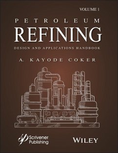
Petroleum Refining Design and Applications Handbook, Volume 1 (eBook, ePUB)


Alle Infos zum eBook verschenken

Petroleum Refining Design and Applications Handbook, Volume 1 (eBook, ePUB)
- Format: ePub
- Merkliste
- Auf die Merkliste
- Bewerten Bewerten
- Teilen
- Produkt teilen
- Produkterinnerung
- Produkterinnerung

Hier können Sie sich einloggen

Bitte loggen Sie sich zunächst in Ihr Kundenkonto ein oder registrieren Sie sich bei bücher.de, um das eBook-Abo tolino select nutzen zu können.
There is a renaissance that is occurring in chemical and process engineering, and it is crucial for today's scientists, engineers, technicians, and operators to stay current. With so many changes over the last few decades in equipment and processes, petroleum refining is almost a living document, constantly needing updating. With no new refineries being built, companies are spending their capital re-tooling and adding on to existing plants. Refineries are like small cities, today, as they grow bigger and bigger and more and more complex. A huge percentage of a refinery can be changed,…mehr
- Geräte: eReader
- mit Kopierschutz
- eBook Hilfe
- Größe: 78.52MB
![Biodesulfurization in Petroleum Refining (eBook, ePUB) Biodesulfurization in Petroleum Refining (eBook, ePUB)]() Nour Shafik El-GendyBiodesulfurization in Petroleum Refining (eBook, ePUB)249,99 €
Nour Shafik El-GendyBiodesulfurization in Petroleum Refining (eBook, ePUB)249,99 €![Petroleum Refining Design and Applications Handbook, Volume 1 (eBook, PDF) Petroleum Refining Design and Applications Handbook, Volume 1 (eBook, PDF)]() A. Kayode CokerPetroleum Refining Design and Applications Handbook, Volume 1 (eBook, PDF)257,99 €
A. Kayode CokerPetroleum Refining Design and Applications Handbook, Volume 1 (eBook, PDF)257,99 €![Modeling and Simulation of Catalytic Reactors for Petroleum Refining (eBook, ePUB) Modeling and Simulation of Catalytic Reactors for Petroleum Refining (eBook, ePUB)]() Jorge AncheytaModeling and Simulation of Catalytic Reactors for Petroleum Refining (eBook, ePUB)127,99 €
Jorge AncheytaModeling and Simulation of Catalytic Reactors for Petroleum Refining (eBook, ePUB)127,99 €![Introduction to Petroleum Engineering (eBook, ePUB) Introduction to Petroleum Engineering (eBook, ePUB)]() John R. FanchiIntroduction to Petroleum Engineering (eBook, ePUB)80,99 €
John R. FanchiIntroduction to Petroleum Engineering (eBook, ePUB)80,99 €![Multiphase Transport of Hydrocarbons in Pipes (eBook, ePUB) Multiphase Transport of Hydrocarbons in Pipes (eBook, ePUB)]() Juan J. Manzano-RuizMultiphase Transport of Hydrocarbons in Pipes (eBook, ePUB)123,99 €
Juan J. Manzano-RuizMultiphase Transport of Hydrocarbons in Pipes (eBook, ePUB)123,99 €![Nanocolloids for Petroleum Engineering (eBook, ePUB) Nanocolloids for Petroleum Engineering (eBook, ePUB)]() Baghir A. SuleimanovNanocolloids for Petroleum Engineering (eBook, ePUB)124,99 €
Baghir A. SuleimanovNanocolloids for Petroleum Engineering (eBook, ePUB)124,99 €![Fuels and Fuel-Additives (eBook, ePUB) Fuels and Fuel-Additives (eBook, ePUB)]() S. P. SrivastavaFuels and Fuel-Additives (eBook, ePUB)94,99 €
S. P. SrivastavaFuels and Fuel-Additives (eBook, ePUB)94,99 €-
-
-
Dieser Download kann aus rechtlichen Gründen nur mit Rechnungsadresse in A, B, BG, CY, CZ, D, DK, EW, E, FIN, F, GR, HR, H, IRL, I, LT, L, LR, M, NL, PL, P, R, S, SLO, SK ausgeliefert werden.
- Produktdetails
- Verlag: John Wiley & Sons
- Seitenzahl: 654
- Erscheinungstermin: 9. August 2018
- Englisch
- ISBN-13: 9781119257103
- Artikelnr.: 53698808
- Verlag: John Wiley & Sons
- Seitenzahl: 654
- Erscheinungstermin: 9. August 2018
- Englisch
- ISBN-13: 9781119257103
- Artikelnr.: 53698808
- Herstellerkennzeichnung Die Herstellerinformationen sind derzeit nicht verfügbar.
P) in Tubular/Fixed-Bed Reactors 205 7.9.4 Catalyst Particle Size 207 7.9.5 Vessel Dimensions 208 7.10 Increased
P 210 7.11 Factors Affecting Reaction Rate 214 7.12 Measurement of Performance 215 7.13 Catalyst-Bed Temperature Profiles 216 7.14 Factors Affecting Hydrocracking Process Operation 217 7.15 Hydrocracking Correlations 217 7.15.1 Maximum Aviation Turbine Kerosene (ATK) Correlations 219 7.15.2 Process Description 220 7.15.3 Fresh Feed and Recycle Liquid System 224 7.15.4 Liquid and Vapor Separators 225 7.15.5 Recycle Gas Compression and Distribution 226 7.15.6 Hydrogen Distribution 226 7.15.7 Control of the Hydrogen System 226 7.15.8 Reactor Design 227 7.16 Hydrocracker Fractionating Unit 228 7.16.1 Mild Vacuum Column 230 7.16.2 Steam Generation 230 7.17 Operating Variables 231 7.18 Hydrotreating Process 234 7.18.1 Process Description 237 7.18.2 Process Variables 237 7.18.3 Hydrotreating Catalysts 240 7.19 Thermodynamics of Hydrotreating 240 7.20 Reaction Kinetics 243 7.21 Naphtha Hydrotreating 245 7.21.1 Hydrotreating Correlations 245 7.21.2 Middle Distillates Hydrotreating 248 7.21.3 Middle Distillate Hydrotreating Correlations 248 7.22 Atmospheric Residue Desulfurization 250 7.22.1 High-Pressure Separator 252 7.22.2 Low-Pressure Separator 252 7.22.3 Hydrogen Sulfide Removal 252 7.22.4 Recycled Gas Compressor 252 7.22.5 Process Water 252 7.22.6 Fractionation Column 253 7.22.7 Operating Conditions of Hydrotreating Processes 253 7.23 Health, Safety and Environment Considerations 258 References 258 8 Catalytic Cracking 259 8.1 Introduction 259 8.2 Fluidized Bed Catalytic Cracking 262 8.2.1 Process Description 262 8.3 Modes of Fluidization 269 8.4 Cracking Reactions 270 8.4.1 Secondary Reactions 272 8.5 Thermodynamics of FCC 273 8.5.1 Transport Phenomena, Reaction Patterns and Kinetic models 273 8.5.2 Three- and Four-Lump kinetic models 276 8.6 Process Design Variables 278 8.6.1 Process Variables 279 8.6.2 Process Operational Variables 280 8.7 Material and Energy Balances 281 8.7.1 Material Balance 281 8.7.2 Energy Balance 282 8.8 Heat Recovery 283 8.9 FCC Yield Correlations 284 8.10 Estimating Potential Yields of FCC Feed 286 8.11 Pollution Control 290 8.12 New Technology 292 8.12.1 Deep Catalytic Cracking 293 8.12.2 Shell's Fluid Catalytic Cracking 294 8.12.3 Fluid Catalytic Cracking High Severity 295 8.12.4 Fluid Catalytic Cracking for Maximum Olefins 295 8.13 Refining/Petrochemical Integration 296 8.14 Metallurgy 296 8.15 Troubleshooting for Fluidized Catalyst Cracking Units 297 8.16 Health, Safety and Environment Considerations 298 8.17 Licensors' Correlations 299 8.18 Simulation and Modeling Strategy 300 References 304 9 Catalytic Reforming and Isomerization 305 9.1 Introduction 305 9.2 Catalytic Reforming 306 9.3 Feed Characterization 306 9.4 Catalytic Reforming Processes 308 9.4.1 Role of Reformer in the Refinery 309 9.4.2 UOP Continuous Catalytic Regeneration (CCR) Reforming Process 310 9.5 Operations of the Reformer Process 312 9.5.1 Effect of Major Variables in Catalytic Reforming 314 9.6 Catalytic Reformer Reactors 316 9.7 Material Balance in Reforming 317 9.8 Reactions 320 9.8.1 Naphthene Dehydrogenation to Cyclohexanes 320 9.8.2 Dehydrocyclization of Paraffins to Aromatics 321 9.8.3 Dehydroisomerization of Alkylcyclopentanes to Aromatics 321 9.8.4 Isomerization of n-Paraffins 321 9.9 Hydrocracking Reactions 322 9.10 Reforming Catalyst 322 9.11 Coke Deposition 324 9.12 Thermodynamics 326 9.13 Kinetic Models 326 9.14 The Reactor Model 326 9.15 Modeling of Naphtha Catalytic Reforming Process 329 9.16 Isomerization 329 9.16.1 Thermodynamics 330 9.16.2 Isomerization Reactions 331 9.17 Sulfolane Extraction Process 331 9.17.1 Sulfolane Extraction Unit (SEU) Corrosion Problems 332 9.17.2 Other Solvents for the Extraction Unit 333 9.18 Aromatic Complex 333 9.18.1 Aromatic Separation 335 9.19 Hydrodealkylation Process 336 9.19.1 Separation of the Reactor Effluents 337 References 337 10 Alkylation and Polymerization Processes 339 10.1 Introduction 339 10.2 Chemistry of Alkylation 340 10.3 Catalysts 342 10.4 Process Variables 343 10.5 Alkylation Feedstocks 345 10.6 Alkylation Products 346 10.7 Sulfuric Acid Alkylation Process 346 10.8 HF Alkylation 347 10.9 Kinetics and Thermodynamics of Alkylation 351 10.10 Polymerization 354 10.11 HF and H2SO4 Mitigating Releases 354 10.12 Corrosion Problems 356 10.13 A New Technology of Alkylation Process Using Ionic Liquid 356 10.14 Chevron - Honeywell UOP Ionic liquid Alkylation 357 10.15 Chemical Release and Flash Fire: A Case Study of the Alkylation Unit at the Delaware City Refining Company (DCRC) Involving Equipment Maintenance Incident 358 References 362 11 Hydrogen Production and Purification 365 11.1 Hydrogen Requirements in a Refinery 365 11.2 Process Chemistry 366 11.3 High-Temperature Shift Conversion 368 11.4 Low-Temperature Shift Conversion 368 11.5 Gas Purification 368 11.6 Purification of Hydrogen Product 369 11.7 Hydrogen Distribution System 370 11.8 Off-Gas Hydrogen Recovery 371 11.9 Pressure Swing Adsorption (PSA) Unit 371 11.10 Refinery Hydrogen Management 375 11.11 Hydrogen Pinch Studies 377 References 379 12 Gas Processing and Acid Gas Removal 381 12.1 Introduction 381 12.2 Diesel Hydrodesulfurization (DHDS) 383 12.3 Hydrotreating Reactions 383 12.4 Gas Processing 388 12.4.1 Natural Gas 388 12.4.2 Gas Processing Methods 389 12.4.3 Reaction Gas Processes 390 12.4.4 Sweetening Process 390 12.4.5 MEROX Process 390 12.5 Sulfur Management 391 12.5.1 Sulfur Recovery Processes 393 12.5.2 Tail Gas Clean Up 401 12.6 Physical Solvent Gas Processes 401 12.6.1 Physical and Chemical Processes 402 12.6.2 Advantages and Disadvantages of the Sulfinol® Process 402 12.7 Carbonate Process 402 12.8 Solution Batch Process 403 12.9 Process Description of Gas Processing using UniSim® Simulation 405 12.10 Gas Dryer (Dehydration) Design 410 12.10.1 The Equations 412 12.10.2 Pressure Drop (
P) 413 12.10.3 Fouled Bed 413 12.11 Kremser-Brown-Sherwood Method-No Heat of Absorption 415 12.11.1 Absorption: Determine Component Absorption in Fixed Tray Tower (Adapted in part from Ref. 12) 415 12.11.2 Absorption: Determine the Number of Trays for Specified Product Absorption 417 12.11.3 Stripping: Determine the Number of Theoretical Trays and Stripping Steam or Gas Rate for a Component Recovery 418 12.11.4 Stripping: Determine Stripping-Medium Rate for a Fixed Recovery 420 12.12 Absorption: Edmister Method 421 12.12.1 Absorption and Stripping Efficiency 427 12.13 Gas Treating Troubleshooting 432 12.13.1 High Exit Gas Dew Point 432 12.13.2 High Glycol Losses 432 12.13.3 Glycol Contamination 432 12.13.4 Poor Glycol Reconcentration 433 12.13.5 Low Glycol Circulation - Glycol Pump 433 12.13.6 High Pressure Drop Across Contactor 433 12.13.7 High Stripping Still Temperature 433 12.13.8 High Reboiler Pressure 433 12.13.9 Firetube Fouling/Hot Spots/Burn Out 433 12.13.10 High Gas Dew Points 433 12.13.11 Cause - Inadequate Glycol Circulation Rate 433 12.13.12 Low Reboiler Temperature 433 12.13.13 Flash Separator Failure 434 12.13.14 Cause - Insufficient Reconcentration of Glycol 434 12.13.15 Cause - Operating Conditions Different from Design 434 12.13.16 Cause - Low Gas Flow Rates 434 12.13.17 High Glycol Loss 434 12.14 Cause - Loss of Glycol Out of Still Column 434 12.15 The ADIP Process 435 12.16 Sour Water Stripping Process 435 References 438 Glossary of Petroleum and Technical Terminology 441 Appendix A Equilibrium K values 533 Appendix B Analytical Techniques 547 Appendix C Physical and Chemical Characteristics of Major Hydrocarbons 557 Appendix D A List of Engineering Process Flow Diagrams and Process Data Sheets 573 Index 623
