Alle Infos zum eBook verschenken
- Format: PDF
- Merkliste
- Auf die Merkliste
- Bewerten Bewerten
- Teilen
- Produkt teilen
- Produkterinnerung
- Produkterinnerung
Hier können Sie sich einloggen
Bitte loggen Sie sich zunächst in Ihr Kundenkonto ein oder registrieren Sie sich bei bücher.de, um das eBook-Abo tolino select nutzen zu können.
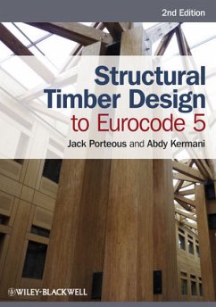
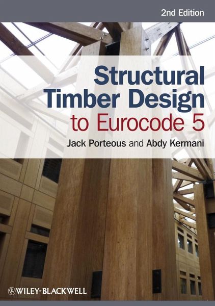
Structural Timber Design to Eurocode 5 provides practising engineers and specialist contractors with comprehensive, detailed information and in-depth guidance on the design of timber structures based on the common rules and rules for buildings in Eurocode 5 - Part 1-1. It will also be of interest to undergraduate and postgraduate students of civil and structural engineering. It provides a step-by-step approach to the design of all of the commonly used timber elements and connections using solid timber, glued laminated timber or wood based structural products, and incorporates the requirements…mehr
- Geräte: PC
- mit Kopierschutz
- eBook Hilfe
- Größe: 64.74MB
- Jack PorteousStructural Timber Design to Eurocode 5 (eBook, ePUB)64,99 €
- Werner SeimStructural Timber Design (eBook, PDF)70,99 €
- Werner SeimIngenieurholzbau - Basiswissen (eBook, PDF)43,99 €
- Rüdiger MeiswinkelDesign and Construction of Nuclear Power Plants (eBook, PDF)52,99 €
- Rolf EligehausenAnchorage in Concrete Construction (eBook, PDF)88,99 €
- Ekkehard FehlingUltra-High Performance Concrete UHPC (eBook, PDF)52,99 €
- Matthias BeckhHyperbolic Structures (eBook, PDF)67,99 €
-
-
-
Dieser Download kann aus rechtlichen Gründen nur mit Rechnungsadresse in A, B, BG, CY, CZ, D, DK, EW, E, FIN, F, GR, HR, H, IRL, I, LT, L, LR, M, NL, PL, P, R, S, SLO, SK ausgeliefert werden.
- Produktdetails
- Verlag: Wiley-IEEE Press
- Seitenzahl: 640
- Erscheinungstermin: 16. April 2013
- Englisch
- ISBN-13: 9781118597286
- Artikelnr.: 38402185
- Verlag: Wiley-IEEE Press
- Seitenzahl: 640
- Erscheinungstermin: 16. April 2013
- Englisch
- ISBN-13: 9781118597286
- Artikelnr.: 38402185
- Herstellerkennzeichnung Die Herstellerinformationen sind derzeit nicht verfügbar.
1 Timber as a Structural Material 1
1.1 Introduction 1
1.2 The structure of timber 2
1.3 Types of timber 3
1.3.1 Softwoods 3
1.3.2 Hardwoods 4
1.4 Natural characteristics of timber 4
1.4.1 Knots 4
1.4.2 Slope of grain 5
1.4.3 Reaction wood 5
1.4.4 Juvenile wood 6
1.4.5 Density and annual ring widths 6
1.4.6 Conversion of timber 7
1.4.7 Seasoning 11
1.4.8 Seasoning defects 11
1.4.9 Cracks and fissures 11
1.4.10 Fungal decay 11
1.5 Strength grading of timber 11
1.5.1 Visual grading 12
1.5.2 Machine grading 12
1.5.3 Strength classes 15
1.6 Section sizes 16
1.7 Engineered wood products (EWPs) 16
1.7.1 Glued-laminated timber (glulam) 18
1.7.2 Cross-laminated timber (CLT or X-Lam) 20
1.7.3 Plywood 21
1.7.4 Laminated veneer lumber (LVL) 25
1.7.5 Laminated Strand Lumber (LSL), TimberStrand® 25
1.7.6 Parallel Strand Lumber (PSL), Parallam® 27
1.7.7 Oriented Strand Board (OSB) 27
1.7.8 Particleboards and fibre composites 39
1.7.9 Thin webbed joists (I-joists) 39
1.7.10 Thin webbed beams (box beams) 41
1.7.11 Structural Insulated Panels (SIPs) 42
1.8 Suspended timber flooring 44
1.9 Adhesive bonding of timber 46
1.10 Preservative treatment for timber 47
1.11 Fire safety and resistance 48
1.12 References 50
2 Introduction to Relevant Eurocodes 52
2.1 Eurocodes: General structure 52
2.2 Eurocode 0: Basis of structural design (EC0) 54
2.2.1 Terms and definitions (EC0, 1.5) 54
2.2.2 Basic requirements (EC0, 2.1) 55
2.2.3 Reliability management (EC0, 2.2) 56
2.2.4 Design working life (EC0, 2.3) 56
2.2.5 Durability (EC0, 2.4) 57
2.2.6 Quality management (EC0, 2.5) 58
2.2.7 Principles of limit state design: General (EC0, 3.1) 58
2.2.8 Design situations (EC0, 3.2) 58
2.2.9 Ultimate limit states (EC0, 3.3) 59
2.2.10 Serviceability limit states (EC0, 3.4) 59
2.2.11 Limit states design (EC0, 3.5) 60
2.2.12 Classification of actions (EC0, 4.1.1) 60
2.2.13 Characteristic values of actions (EC0, 4.1.2) 60
2.2.14 Other representative values of variable actions (EC0, 4.1.3) 61
2.2.15 Material and product properties (EC0, 4.2) 62
2.2.16 Structural analysis (EC0, 5.1) 62
2.2.17 Verification by the partial factor method: General (EC0, 6.1) 65
2.2.18 Design values of actions (EC0, 6.3.1) 65
2.2.19 Design values of the effects of actions (EC0, 6.3.2) 66
2.2.20 Design values of material or product properties (EC0, 6.3.3) 66
2.2.21 Factors applied to a design strength at the ULS 71
2.2.22 Design values of geometrical data (EC0, 6.3.4) 71
2.2.23 Design resistance (EC0, 6.3.5) 71
2.2.24 Ultimate limit states (EC0, 6.4.1-6.4.5) 73
2.2.25 Serviceability limit states: General (EC0, 6.5) 77
2.3 Eurocode 5: Design of Timber Structures - Part 1-1: General - Common
Rules and Rules for Buildings (EC5) 79
2.3.1 General matters 79
2.3.2 Serviceability limit states (EC5, 2.2.3) 80
2.3.3 Load duration and moisture influences on strength (EC5, 2.3.2.1) 84
2.3.4 Load duration and moisture influences on deformations (EC5, 2.3.2.2)
84
2.3.5 Stress-strain relations (EC5, 3.1.2) 87
2.3.6 Size and stress distribution effects (EC5, 3.2, 3.3, 3.4 and 6.4.3)
87
2.3.7 System strength (EC5, 6.6) 90
2.4 Symbols 93
2.5 References 98
3 Using Mathcad® for Design Calculations 100
3.1 Introduction 100
3.2 What is Mathcad? 100
3.3 What does Mathcad do? 101
3.3.1 A simple calculation 101
3.3.2 Definitions and variables 102
3.3.3 Entering text 102
3.3.4 Working with units 103
3.3.5 Commonly used Mathcad functions 104
3.4 Summary 106
3.5 References 106
4 Design of Members Subjected to Flexure 107
4.1 Introduction 107
4.2 Design considerations 107
4.3 Design value of the effect of actions 109
4.4 Member span 109
4.5 Design for Ultimate Limit States (ULS) 110
4.5.1 Bending 110
4.5.2 Shear 121
4.5.3 Bearing (compression perpendicular to the grain) 127
4.5.4 Torsion 131
4.5.5 Combined shear and torsion 133
4.6 Design for Serviceability Limit States (SLS) 133
4.6.1 Deformation 134
4.6.2 Vibration 137
4.7 References 142
4.8 Examples 143
5 Design of Members and Walls Subjected to Axial or Combined Axial and
Flexural Actions 158
5.1 Introduction 158
5.2 Design considerations 158
5.3 Design of members subjected to axial actions 160
5.3.1 Members subjected to axial compression 160
5.3.2 Members subjected to compression at an angle to the grain 170
5.3.3 Members subjected to axial tension 172
5.4 Members subjected to combined bending and axial loading 174
5.4.1 Where lateral torsional instability due to bending about the major
axis will not occur 174
5.4.2 Lateral torsional instability under the effect of bending about the
major axis 178
5.4.3 Members subjected to combined bending and axial tension 179
5.5 Design of stud walls 179
5.5.1 Design of load-bearing walls 180
5.5.2 Out of plane deflection of load-bearing stud walls (and columns) 186
5.6 References 188
5.7 Examples 189
6 Design of Glued-Laminated Members 216
6.1 Introduction 216
6.2 Design considerations 218
6.3 General 218
6.3.1 Horizontal and vertical glued-laminated timber 218
6.3.2 Design methodology 219
6.4 Design of glued-laminated members with tapered, curved or pitched
curved profiles (also applicable to LVL members) 223
6.4.1 Design of single tapered beams 223
6.4.2 Design of double tapered beams, curved and pitched cambered beams 228
6.4.3 Design of double tapered beams, curved and pitched cambered beams
subjected to combined shear and tension perpendicular to the grain 234
6.5 Finger joints 234
Annex 6.1 Deflection formulae for simply supported tapered and double
tapered beams subjected to a point load at mid-span or to a uniformly
distributed load. 234
Annex 6.2 Graphical representation of factors k§¿ and kp used in the
derivation of the bending and radial stresses in the apex zone of double
tapered curved and pitched cambered beams. 237
6.6 References 238
6.7 Examples 239
7 Design of Composite Timber and Wood-Based Sections 258
7.1 Introduction 258
7.2 Design considerations 259
7.3 Design of glued composite sections 260
7.3.1 Glued thin webbed beams 260
7.3.2 Glued thin flanged beams (stressed skin panels) 274
7.4 References 283
7.5 Examples 283
8 Design of Built-Up Columns 311
8.1 Introduction 311
8.2 Design considerations 311
8.3 General 312
8.4 Bending stiffness of built-up columns 313
8.4.1 The effective bending stiffness of built-up sections about the strong
(y-y) axis 314
8.4.2 The effective bending stiffness of built-up sections about the z-z
axis 316
8.4.3 Design procedure 318
8.4.4 Built-up sections - spaced columns 323
8.4.5 Built-up sections - latticed columns 327
8.5 Combined axial loading and moment 331
8.6 Effect of creep at the ULS 332
8.7 References 333
8.8 Examples 333
9 Design of Stability Bracing, Floor and Wall Diaphragms 357
9.1 Introduction 357
9.2 Design considerations 358
9.3 Lateral bracing 358
9.3.1 General 358
9.3.2 Bracing of single members (subjected to direct compression) by local
support 360
9.3.3 Bracing of single members (subjected to bending) by local support 363
9.3.4 Bracing for beam, truss or column systems 364
9.4 Floor and roof diaphragms 368
9.4.1 Limitations on the applicability of the method 368
9.4.2 Simplified design procedure 368
9.5 The in-plane racking resistance of timber walls under horizontal and
vertical loading 370
9.6 References 372
9.7 Examples 373
10 Design of Metal Dowel-type Connections 383
10.1 Introduction 383
10.1.1 Metal dowel-type fasteners 383
10.2 Design considerations 387
10.3 Failure theory and strength equations for laterally loaded connections
formed using metal dowel fasteners 389
10.3.1 Dowel diameter 395
10.3.2 Characteristic fastener yield moment (My,Rk) 397
10.3.3 Characteristic embedment strength (fh,k) 398
10.3.4 Member thickness, t1 and t2 402
10.3.5 Friction effects and axial withdrawal of the fastener 403
10.3.6 Brittle failure 406
10.4 Multiple dowel fasteners loaded laterally 412
10.4.1 The effective number of fasteners 413
10.4.2 Alternating forces in connections 416
10.5 Design strength of a laterally loaded metal dowel connection 416
10.5.1 Loaded parallel to the grain 416
10.5.2 Loaded perpendicular to the grain 417
10.6 Examples of the design of connections using metal dowel-type fasteners
418
10.7 Multiple shear plane connections 418
10.8 Axial loading of metal dowel connection systems 420
10.8.1 Axially loaded nails 420
10.8.2 Axially loaded bolts 423
10.8.3 Axially loaded dowels 423
10.8.4 Axially loaded screws 423
10.9 Combined laterally and axially loaded metal dowel connections 427
10.10 Lateral stiffness of metal dowel connections at the SLS and ULS 428
10.11 Frame analysis incorporating the effect of lateral movement in metal
dowel fastener connections 435
10.12 References 436
10.13 Examples 437
11 Design of Joints with Connectors 473
11.1 Introduction 473
11.2 Design considerations 473
11.3 Toothed-plate connectors 474
11.3.1 Strength behaviour 474
11.4 Ring and shear-plate connectors 480
11.4.1 Strength behaviour 480
11.5 Multiple shear plane connections 487
11.6 Brittle failure due to connection forces at an angle to the grain 487
11.7 Alternating forces in connections 487
11.8 Design strength of a laterally loaded connection 488
11.8.1 Loaded parallel to the grain 488
11.8.2 Loaded perpendicular to the grain 489
11.8.3 Loaded at an angle to the grain 489
11.9 Stiffness behaviour of toothed-plate, ring and shear-plate connectors
489
11.10 Frame analysis incorporating the effect of lateral movement in
connections formed using toothed-plate, split-ring or shear-plate
connectors 491
11.11 References 491
11.12 Examples 491
12 Moment Capacity of Connections Formed with Metal Dowel Fasteners or
Connectors 504
12.1 Introduction 504
12.2 Design considerations 505
12.3 The effective number of fasteners in a row in a moment connection 505
12.4 Brittle failure 506
12.5 Moment behaviour in timber connections: Rigid model behaviour 507
12.5.1 Assumptions in the connection design procedure 507
12.5.2 Connection design procedure 509
12.5.3 Shear strength and force component checks on connections subjected
to a moment and lateral forces 512
12.6 The analysis of structures with semi-rigid connections 519
12.6.1 The stiffness of semi-rigid moment connections 520
12.6.2 The analysis of beams with semi-rigid end connections 522
12.7 References 526
12.8 Examples 526
13 Racking Design of Multi-storey Platform Framed Wall Construction 555
13.1 Introduction 555
13.2 Conceptual design 555
13.3 Design requirements of racking walls 558
13.4 Loading 558
13.5 Basis of Method A 560
13.5.1 General requirements 560
13.5.2 Theoretical basis of the method 562
13.5.3 The EC5 procedure 564
13.6 Basis of the racking method in PD6693-1 573
13.6.1 General requirements 573
13.6.2 Theoretical basis of the method 575
13.6.3 The PD6693-1 procedure 579
13.7 References 586
13.8 Examples 587
Appendix A: Weights of Building Materials 610
Appendix B: Related British Standards for Timber Engineering in Buildings
612
Appendix C: Possible Revisions to be Addressed in a Corrigendum to EN
1995-1-1:2004 + A1:2008 614
Index 618
The Example Worksheets Order Form 624