H G Fisher, H S Forrest, Stanley S Grossel, J E Huff, A R Muller, J A Noronha, D A Shaw, B J Tilley
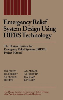
Emergency Relief System Design Using Diers Technology
The Design Institute for Emergency Relief Systems (Diers) Project Manual
H G Fisher, H S Forrest, Stanley S Grossel, J E Huff, A R Muller, J A Noronha, D A Shaw, B J Tilley
Emergency Relief System Design Using Diers Technology
The Design Institute for Emergency Relief Systems (Diers) Project Manual
- Gebundenes Buch
- Merkliste
- Auf die Merkliste
- Bewerten Bewerten
- Teilen
- Produkt teilen
- Produkterinnerung
- Produkterinnerung
OSHA (29 CFR 1910.119) has recognized AIChE/DIERS two-phase flow publications as examples of "good engineering practice" for process safety management of highly hazardous materials. The prediction of when two-phase flow venting will occur, and the applicability of various sizing methods for two-phase vapor-liquid flashing flow, is of particular interest when designing emergency relief systems to handle runaway reactions. This comprehensive sourcebook brings together a wealth of information on methods that can be used to safely size emergency relief systems for two-phase vapor-liquid flow for…mehr
Andere Kunden interessierten sich auch für
![Industrial Emergency Preparedness Industrial Emergency Preparedness]() Robert B KellyIndustrial Emergency Preparedness277,99 €
Robert B KellyIndustrial Emergency Preparedness277,99 €![Guidelines for Pressure Relief and Effluent Handling Systems Guidelines for Pressure Relief and Effluent Handling Systems]() Center for Chemical Process Safety (CCPS)Guidelines for Pressure Relief and Effluent Handling Systems364,99 €
Center for Chemical Process Safety (CCPS)Guidelines for Pressure Relief and Effluent Handling Systems364,99 €![Emergency Incident Risk Management Emergency Incident Risk Management]() Jonathan D KippEmergency Incident Risk Management175,99 €
Jonathan D KippEmergency Incident Risk Management175,99 €![Local Emergency Planning Committee Guidebook Local Emergency Planning Committee Guidebook]() R J WalterLocal Emergency Planning Committee Guidebook122,99 €
R J WalterLocal Emergency Planning Committee Guidebook122,99 €![Deflagration and Detonation Flame Arresters Deflagration and Detonation Flame Arresters]() Stanley S GrosselDeflagration and Detonation Flame Arresters183,99 €
Stanley S GrosselDeflagration and Detonation Flame Arresters183,99 €![Guidelines for Improving Plant Reliability Through Data Collection and Analysis Guidelines for Improving Plant Reliability Through Data Collection and Analysis]() Center for Chemical Process Safety (CCPS)Guidelines for Improving Plant Reliability Through Data Collection and Analysis246,99 €
Center for Chemical Process Safety (CCPS)Guidelines for Improving Plant Reliability Through Data Collection and Analysis246,99 €![Spray Dryers Spray Dryers]() American Institute of Chemical Engineers (Aiche)Spray Dryers221,99 €
American Institute of Chemical Engineers (Aiche)Spray Dryers221,99 €-
-
-
OSHA (29 CFR 1910.119) has recognized AIChE/DIERS two-phase flow publications as examples of "good engineering practice" for process safety management of highly hazardous materials. The prediction of when two-phase flow venting will occur, and the applicability of various sizing methods for two-phase vapor-liquid flashing flow, is of particular interest when designing emergency relief systems to handle runaway reactions. This comprehensive sourcebook brings together a wealth of information on methods that can be used to safely size emergency relief systems for two-phase vapor-liquid flow for flashing or frozen, viscous or nonviscous fluids. Design methodologies are illustrated by selected sample problems. Written by industrial experts in the safety field, this book will be invaluable to those charged with operating, designing, or managing today's and tomorrow's chemical process industry facilities.
Hinweis: Dieser Artikel kann nur an eine deutsche Lieferadresse ausgeliefert werden.
Hinweis: Dieser Artikel kann nur an eine deutsche Lieferadresse ausgeliefert werden.
Produktdetails
- Produktdetails
- Verlag: Wiley
- Seitenzahl: 576
- Erscheinungstermin: 15. April 1993
- Englisch
- Abmessung: 235mm x 157mm x 35mm
- Gewicht: 976g
- ISBN-13: 9780816905683
- ISBN-10: 0816905681
- Artikelnr.: 24556730
- Herstellerkennzeichnung
- Libri GmbH
- Europaallee 1
- 36244 Bad Hersfeld
- gpsr@libri.de
- Verlag: Wiley
- Seitenzahl: 576
- Erscheinungstermin: 15. April 1993
- Englisch
- Abmessung: 235mm x 157mm x 35mm
- Gewicht: 976g
- ISBN-13: 9780816905683
- ISBN-10: 0816905681
- Artikelnr.: 24556730
- Herstellerkennzeichnung
- Libri GmbH
- Europaallee 1
- 36244 Bad Hersfeld
- gpsr@libri.de
H. G. Fisher is the author of Emergency Relief System Design Using DIERS Technology: The Design Institute for Emergency Relief Systems (DIERS) Project Manual, published by Wiley. H. S. Forrest is the author of Emergency Relief System Design Using DIERS Technology: The Design Institute for Emergency Relief Systems (DIERS) Project Manual, published by Wiley. Stanley S. Grossel is the author of Emergency Relief System Design Using DIERS Technology: The Design Institute for Emergency Relief Systems (DIERS) Project Manual, published by Wiley. J. E. Huff is the author of Emergency Relief System Design Using DIERS Technology: The Design Institute for Emergency Relief Systems (DIERS) Project Manual, published by Wiley. A. R. Muller is the author of Emergency Relief System Design Using DIERS Technology: The Design Institute for Emergency Relief Systems (DIERS) Project Manual, published by Wiley. J. A. Noronha is the author of Emergency Relief System Design Using DIERS Technology: The Design Institute for Emergency Relief Systems (DIERS) Project Manual, published by Wiley. D. A. Shaw is the author of Emergency Relief System Design Using DIERS Technology: The Design Institute for Emergency Relief Systems (DIERS) Project Manual, published by Wiley. B. J. Tilley is the author of Emergency Relief System Design Using DIERS Technology: The Design Institute for Emergency Relief Systems (DIERS) Project Manual, published by Wiley.
Preface.
Introduction.
1. Overview.
2. Design Institute for Emergency Relief Systems (DIERS).
3. A Strategy for Major Accidental Release Prevention.
4. A Strategy for Emergency Relief System Design.
5. An Approach to Emergency Relief System Design Assessment.
6. Two-Phase Vapor-Liquid Flow.
7. Two-Phase Vapor-Liquid Flow Onset and Disengagement.
8. Two-Phase Vapor-Liquid Hydrodynamics.
9. DIERS Bench-Scale Apparatus.
10. Runaway Reaction Emergency Relief System Design Computer Program.
11. References.
Appendix A. DIERS Committees.
Appendix B. DIERS Sponsors.
Appendix C. DIERS Contractors.
Chapter I. Vapor Disengagement Dynamics.
1. Overview.
1.1 Vapor Disengagement Dynamics.
1.2 Design Considerations.
2. Detailed Discussion.
2.1 Open Literature References.
2.2 Project Manual.
3. References.
Appendix I-A The Coupling Equation and Flow Models.
Appendix I-B Best Estimate Procedure to Calculate Two-Phase Vapor-Liquid
Flow Onset/Disengagement.
Appendix I-C Fluid Behavior in Venting Vessels.
Appendix I-D Energy and Material Balance Derivations for Emergency Pressure
Relief of Vessels.
Annex I-D1 Internal Energy and Venting Calculations.
Chapter II. Pressure Relief System Flow.
1. Introduction.
1.1 Scope.
1.2 Organization.
1.3 Special Terminology.
2. Recommended Design Methods.
2.1 Newtonian Flow.
2.2 Complex Fluids.
2.3 Useful Approximations.
3. Technology Base.
3.1 General Flow Equations.
3.2 Nozzle Flow Models.
3.3 Sharp Reductions.
3.4 Pressure Recovery/Expansions/Equilibrations.
3.5 Pipe Flow.
3.6 Application to Pressure Relief System Elements.
3.7 Networks.
3.8 Complex Fluids.
4. Nomenclature.
5. Acknowledgments.
6. References.
Appendix II-A Thermophysical Property Requirements.
Appendix II-B Equilibrium Flash Calculations.
Appendix II-C Model Parameters for Pipe Entrance Sections.
Appendix II-D Computer Routines in SAFIRE Program.
Appendix II-E Example Problems.
Appendix II-F Generalized Correlations and Design Charts.
Chapter III. DIERS Phase III Large-Scale Integral Tests.
1. Summary.
2. Introduction.
2.1 Program Objectives.
2.2 Program Description.
3. Test Configurations.
4. Test Results.
4.1 Tests T1 to T8
4.2 Tests V32-W1 to V32-W8.
4.3 Tests T9, T10, T11, T14, and T15.
4.4 Tests T12 and T13.
4.5 Tests T20.
4.6 Tests T17 and T18.
4.7 Tests T21, T22, T23, and T24.
4.8 ICRE Tests 32-6 to 32-11.
4.9 ICRE Tests 2000-1 to 2000-5.
4.10 ICRE Tests 32-14, 32-15, and 32-18.
5. Acknowledgments.
6. References.
Appendix III-A Test Configurations.
Appendix III-B Experimental Results and Model Comparisons.
Appendix III-C Kinetics Model for Styrene Polymerizations.
Chapter IV. High Viscosity Flashing Two-Phase Flow.
1. Introduction.
1.1 General Discussion of High Viscosity Flow in Relief Systems.
1.2 Why High Viscosity Systems Require Special Consideration.
1.3 Necessity for Conservatism.
2. Summary of DIERS High Viscosity Relief Flow Tests.
2.1 Project Overview.
2.2 Styrene Reactive Tests.
2.3 Small-Scale Rubber Cement Bottom-Vented tests.
2.4 Large-Scale Rubber Cement Tests.
2.5 Large-Scale Polystyrene-Ethylbenzene Bottom-Vented Tests.
3. Recommended Design Practices.
3.1 Theory and Scaling for Highly Viscous Systems.
3.2 General Equations for Newtonian Fluids.
3.3 Approximate Momentum Balances for Scaling Power-Law and Newtonian
Fluids.
3.4 Scaling Using Integrated Approximate Momentum Balance for Newtonian
Fluids.
3.5 Scaling Using Approximate Momentum Balance for Power-Law Fluids.
4. Unanswered Questions about High Viscosity Flow.
4.1 Uncertainties.
5. References.
Appendix IV-A Simplified Theory and Sample Problems.
Chapter V. Containment, Disposal, and Mechanical Design.
1. Introduction.
2. Blowdown in Drum Design.
2.1 Types of Knock-Out (Blowdown) Drums and Catchtanks.
2.2 Sizing of Blowdown Drums.
3. Disposal of Vapors from Blowdown Drums.
3.1 Direct Discharge to the Atmosphere.
3.2 Discharge through a Scrubber.
3.3 Discharge through a Vent Condenser.
3.4 Discharge to a Flare Stack or Incinerator.
4. Mechanical Design.
4.1 Vent Piping Considerations.
4.2 Catchtank Mechanical Design and Safety Considerations.
4.3 Reaction Forces-General.
4.4 Reaction Forces Equations.
4.5 Reaction Forces on Safety Valve Nozzles/Piping.
4.6 Reaction Forces from Rupture Disk Discharge.
4.7 Transient Effects of Reaction Forces, Rupture Disk Discharge.
4.8 Thrust Restraint Design.
4.9 Other Blowdown Load Considerations.
5. References.
Chapter VI. DIERS Bench-Scale Apparatus.
1. Background.
1.1 DIERS Requirements for a Bench-Scale Apparatus.
1.2 Limitations of Previous Test Equipment.
2. How the Test Methodology Fits into the Overall Process Safety Design.
2.1 Requests.
2.2 Worst Credible Incident Scenario.
2.3 Screening Tests.
2.4 DIERS Venting Tests and Analysis.
2.5 Recommendations.
3. Description of the DIERS Bench-Scale Apparatus.
3.1 Schematic Description of Apparatus.
3.2 Apparatus Control and Data Recording.
3.3 Test Cell Configurations.
4. Emergency Relief System (ERS) Sizing Using the DIERS Bench-Scale
Apparatus.
4.1 Emergency Relief System (ERS) Overview.
4.2 Functions of the Bench-Scale Apparatus.
4.3 Onset/Disengagement Behavior Testing.
4.4 Flow Rate Calculation/Viscosity Characterization.
4.5 Characterization of Runaway Reaction Behavior.
4.6 ERS Design-Analytical Methods/FAI Nomograph.
4.7 ERS Design-Area: Charge Scaling (Top Vent Test/Top ERS Device).
4.8 ERS Design-Area: Charge Scaling/Scaling Equation Method (Bottom Vent
Test/Top or Bottom ERS Devices).
4.9 Limitations on Area: Charge Scaling for ERS Design.
5. References.
Appendix V1-A Experimental ERS Sizing-Some Do and Do Not Recommendations.
Chapter VII. SAFIRE Computer Program for Emergency Relief Sizing.
1. Background.
1.1 History.
1.2 Overview.
2. Program Description.
2.1 Overall Architecture.
2.2 Pure-Component Physical Properties.
2.3 Mixture handling Rules.
2.4 Flash Calculations.
2.5 Chemical Reactions.
2.6 Vent Flow Calculations.
2.7 Vessel Hydrodynamics.
2.8 External Heat Fluxes.
2.9 Mass and Energy Balances.
3. Data Input.
4. Sample Problem.
5. Experience with Program.
6. References.
Appendix VII-A Input Data Forms.
Appendix VII-B Sample Input/Output.
Index.

