- Gebundenes Buch
- Merkliste
- Auf die Merkliste
- Bewerten Bewerten
- Teilen
- Produkt teilen
- Produkterinnerung
- Produkterinnerung
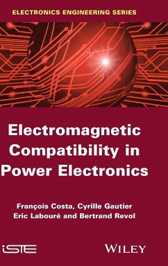
Scientists largely attribute the recent deterioration of the electromagnetic environment to power electronics. This realization has spurred the study of methodical approaches to electromagnetic compatibility designs as explored in this text. The book addresses major challenges, such as handling numerous parameters vital to predicting electro magnetic effects and achieving compliance with line-harmonics norms, while proposing potential solutions.
Andere Kunden interessierten sich auch für
![Computational Methods in Electromagnetic Compatibility Computational Methods in Electromagnetic Compatibility]() Dragan PoljakComputational Methods in Electromagnetic Compatibility136,99 €
Dragan PoljakComputational Methods in Electromagnetic Compatibility136,99 €![Electromagnetic Compatibility Engineering Electromagnetic Compatibility Engineering]() Henry W. OttElectromagnetic Compatibility Engineering160,99 €
Henry W. OttElectromagnetic Compatibility Engineering160,99 €![Advanced Modeling in Computational Electromagnetic Compatibility Advanced Modeling in Computational Electromagnetic Compatibility]() Dragan PoljakAdvanced Modeling in Computational Electromagnetic Compatibility221,99 €
Dragan PoljakAdvanced Modeling in Computational Electromagnetic Compatibility221,99 €![Engineering Electromagnetic Compatibility Engineering Electromagnetic Compatibility]() W. Prasad KodaliEngineering Electromagnetic Compatibility231,99 €
W. Prasad KodaliEngineering Electromagnetic Compatibility231,99 €![Principles of Electric Machines and Power Electronics Principles of Electric Machines and Power Electronics]() P C SenPrinciples of Electric Machines and Power Electronics363,99 €
P C SenPrinciples of Electric Machines and Power Electronics363,99 €![Principles and Techniques of Electromagnetic Compatibility Principles and Techniques of Electromagnetic Compatibility]() Christos ChristopoulosPrinciples and Techniques of Electromagnetic Compatibility196,99 €
Christos ChristopoulosPrinciples and Techniques of Electromagnetic Compatibility196,99 €![Electromagnetic Compatibility Electromagnetic Compatibility]() Donald G BakerElectromagnetic Compatibility152,99 €
Donald G BakerElectromagnetic Compatibility152,99 €-
-
-
Scientists largely attribute the recent deterioration of the electromagnetic environment to power electronics. This realization has spurred the study of methodical approaches to electromagnetic compatibility designs as explored in this text. The book addresses major challenges, such as handling numerous parameters vital to predicting electro magnetic effects and achieving compliance with line-harmonics norms, while proposing potential solutions.
Hinweis: Dieser Artikel kann nur an eine deutsche Lieferadresse ausgeliefert werden.
Hinweis: Dieser Artikel kann nur an eine deutsche Lieferadresse ausgeliefert werden.
Produktdetails
- Produktdetails
- Verlag: Wiley
- Seitenzahl: 287
- Erscheinungstermin: 3. Februar 2014
- Englisch
- Abmessung: 240mm x 161mm x 20mm
- Gewicht: 601g
- ISBN-13: 9781848215047
- ISBN-10: 1848215045
- Artikelnr.: 37006007
- Herstellerkennzeichnung
- Libri GmbH
- Europaallee 1
- 36244 Bad Hersfeld
- gpsr@libri.de
- Verlag: Wiley
- Seitenzahl: 287
- Erscheinungstermin: 3. Februar 2014
- Englisch
- Abmessung: 240mm x 161mm x 20mm
- Gewicht: 601g
- ISBN-13: 9781848215047
- ISBN-10: 1848215045
- Artikelnr.: 37006007
- Herstellerkennzeichnung
- Libri GmbH
- Europaallee 1
- 36244 Bad Hersfeld
- gpsr@libri.de
François Costa, Professor at IUFM de Créteil. Eric Laboure, Lecturer.
Chapter 1. Phenomena of Perturbation in Electrical Systems 1
1.1. Electromagnetic perturbations in energy systems 1
1.1.1. Introduction 1
1.2. Power grid harmonics 6
1.2.1 Presentation 6
1.2.2. Characterization of the quality of electrical energy 8
1.2.3. Relevant standards for harmonic emissions 10
1.2.4. Classification of appliances 11
1.2.5. The limits of harmonic currents 12
1.2.6. Examples of observations of harmonic currents 15
1.2.7. Fluorescent lighting scenario 16
1.2.8. Practical scenario of the improvement of the total harmonic
distortion generated by a variable-frequency drive 20
1.2.9. Converter with sinusoidal absorption 24
1.3. Common-mode and differential-mode conducted perturbations. 29
1.3.1. Common mode and differential mode 30
1.3.2. Crosstalk 41
1.4. Measuring electromagnetic perturbations 44
1.4.1. The line impedance stabilization network 44
1.4.2. Current sensors 46
1.4.3. Antennae 53
1.4.4. Spectrum analyzer 65
1.5. The standards 72
1.6. Bibliography 73
Chapter 2. Fundamental Principles 75
2.1. Sources of noise: the switching cell and its control 75
2.1.1. Origin of conducted and radiated perturbations in static converters
76
2.2. Modeling 77
2.2.1. Simple model of the switching cell 77
2.2.2. More complex model of the switching cell 82
2.3. Characterization of coupling functions and parasitic elements 86
2.3.1. Passive components and differential-mode effects 86
2.3.2. Invisible parasitic elements and common-mode effects 89
2.3.3. Parasitic effects contributing to undesirable couplings 91
2.4. Electromagnetic compatibility study of a practical scenario: the Buck
chopper 103
2.4.1. Description of the case study 104
2.4.2. Influence of the design parameters of the converter 109
2.4.3. Influence of technological parameters and control 111
2.4.4. Other sources of switching noise 112
2.4.5. Other switching modes: soft switching, advantages and constraints
113
2.5. EMC study of an insulated DC-DC fly back power supply 114
2.5.1. Description of the device 114
2.5.2. Creation of the circuit model 117
2.5.3. Analysis of switchings in the structure 121
2.5.4. Electric simulation of the complete structure 123
2.6. Corrected exercise number 1: conducted perturbations of a step-up
chopper 127
2.7. Answers with comments 130
2.8. Bibliography 141
Chapter 3. EMC of Complex Electrical Energy Conversion Systems:
Electromagnetic Actuators 143
3.1. How to define a complex system? 143
3.2. Qualitative study 145
3.2.1. Description of the conversion chain 145
3.2.2. Reminder of the standards. 147
3.2.3. Propagation methods 149
3.3. Modeling in frequency domain 152
3.3.1. Linearization of the switching cell 152
3.3.2. Modeling of the perturbation sources 157
3.4. Frequency-based representation of an inverter 173
3.4.1. Equivalent common-mode source - simplified diagram 173
3.4.2. Differential-mode influence 176
3.4.3. Proposed frequency-based diagram 178
3.5. Modeling of the cables and motors 179
3.5.1. Estimation of the primary parameters of the power cables 179
3.5.2. High-frequency model of an asynchronous machine 185
3.6. Connection of the cable and the motor 196
3.6.1. Total impedance read by the variable-speed drive 196
3.6.2. Measuring the total common-mode impedance 197
3.7. Results 198
3.7.1. Time-based simulation and frequency-based simulation 198
3.7.2. Measurement versus simulation 200
3.8. Passing from the time domain to the frequency domain: circuit
simulations 201
3.9. Conclusion 204
3.10. Bibliography 205
Chapter 4. Concrete Study of Solutions for the Reduction of Electromagnetic
Perturbations 207
4.1. Concrete study of solutions for the reduction of electromagnetic
perturbations 207
4.1.1. Introduction 207
4.2. Filtering conducted emissions: analysis and conceptual design of
common-mode filters 212
4.2.1. Introduction 212
4.2.2. Description of a common-mode filter 214
4.3. Case study: determining a common-mode filter for a variable-speed
drive 221
4.3.1. Equivalent model of the drive 221
4.3.2. Filter simulated using perfect components 223
4.3.3. Effect of the parasitic elements of components 226
4.4. Design and optimization components 230
4.4.1. Study of capacitors 230
4.4.2. Study of the common-mode toric inductance 232
4.4.3. Results 237
4.5. Conclusion 239
4.5.1. Corrected exercise: filtering the conducted perturbations of a
step-up chopper 239
4.6. Shielding 248
4.6.1. Introduction 248
4.6.2. Breakdown of shielding effects 249
4.6.3. Materials 252
4.6.4. Wave impedance 257
4.6.5. Expression of attenuations 264
4.6.6. Global attenuation: case study 269
4.6.7. Shielding issues for magnetic fields in low frequency 273
4.7. Conclusion 275
4.8. Bibliography 276
Index 279

