- Gebundenes Buch
- Merkliste
- Auf die Merkliste
- Bewerten Bewerten
- Teilen
- Produkt teilen
- Produkterinnerung
- Produkterinnerung
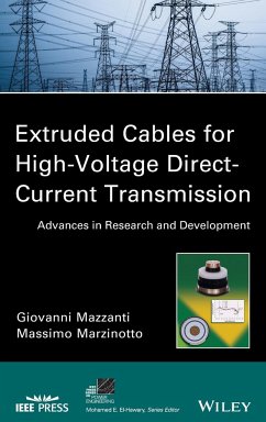
The only book on the market that provides current, necessary, and comprehensive technical knowledge of extruded cables and high-voltage direct-current transmission
This is the first book to fully address the technical aspects of high-voltage direct-current (HVDC) link projects with extruded cables. It covers design and engineering techniques for cable lines, insulation materials, and accessories, as well as cable performance and life span and reliability issues.
Beginning with a discussion on the fundamentals of HVDC cable transmission theory, Extruded Cables for High-Voltage…mehr
Andere Kunden interessierten sich auch für
![Power and Communication Cables Power and Communication Cables]() Ray BartnikasPower and Communication Cables257,99 €
Ray BartnikasPower and Communication Cables257,99 €![Vsc-Facts-Hvdc Vsc-Facts-Hvdc]() Enrique E. AchaVsc-Facts-Hvdc149,99 €
Enrique E. AchaVsc-Facts-Hvdc149,99 €![Hvdc Transmission Hvdc Transmission]() Chan-Ki KimHvdc Transmission190,99 €
Chan-Ki KimHvdc Transmission190,99 €![High Voltage Protection for Telecommunications High Voltage Protection for Telecommunications]() Steven W. BlumeHigh Voltage Protection for Telecommunications123,99 €
Steven W. BlumeHigh Voltage Protection for Telecommunications123,99 €![Handbook of Power Systems Engineering with Power Electronics Applications Handbook of Power Systems Engineering with Power Electronics Applications]() Yoshihide HaseHandbook of Power Systems Engineering with Power Electronics Applications199,99 €
Yoshihide HaseHandbook of Power Systems Engineering with Power Electronics Applications199,99 €![Power Quality Power Quality]() Bhim SinghPower Quality165,99 €
Bhim SinghPower Quality165,99 €![Analysis of Multiconductor Transmission Lines Analysis of Multiconductor Transmission Lines]() Clayton R. PaulAnalysis of Multiconductor Transmission Lines262,99 €
Clayton R. PaulAnalysis of Multiconductor Transmission Lines262,99 €-
-
-
The only book on the market that provides current, necessary, and comprehensive technical knowledge of extruded cables and high-voltage direct-current transmission
This is the first book to fully address the technical aspects of high-voltage direct-current (HVDC) link projects with extruded cables. It covers design and engineering techniques for cable lines, insulation materials, and accessories, as well as cable performance and life span and reliability issues.
Beginning with a discussion on the fundamentals of HVDC cable transmission theory, Extruded Cables for High-Voltage Direct-Current Transmission: Advances in Research and Development covers:
Both the cable and the accessories (joints and terminations), each of which affects cable line performance
The basic designs of HVDC cables-including a comparison of mass insulated non-draining cables with extruded HVDC cables
The theoretical elements on which the design of HVDC cables is based-highlighting the differences between HVAC and HVDC cables
Space charge-related problems that have a critical impact on extruded insulation for HVDC application
Recent advances in extruded compounds for HVDC cables such as additives and nano-fillers
The improved design of extruded HVDC cable systems-with emphasis on design aspects relevant to accessories
Cable line reliability problems and the impact on cable system design
Including more than 200 illustrations, Extruded Cables for High-Voltage Direct-Current Transmission fills a gap in the field, providing power cable engineers with complete, up-to-date guidance on HVDC cable lines with extruded insulation.
Hinweis: Dieser Artikel kann nur an eine deutsche Lieferadresse ausgeliefert werden.
Produktdetails
- Produktdetails
- IEEE Press Series on Power Engineering .
- Verlag: Wiley & Sons
- 1. Auflage
- Seitenzahl: 384
- Erscheinungstermin: 5. August 2013
- Englisch
- Abmessung: 240mm x 161mm x 25mm
- Gewicht: 781g
- ISBN-13: 9781118096666
- ISBN-10: 1118096665
- Artikelnr.: 36724744
- Herstellerkennzeichnung
- Libri GmbH
- Europaallee 1
- 36244 Bad Hersfeld
- gpsr@libri.de
GIOVANNI MAZZANTI, PHD, is an Associate Professor at the University of Bologna where he teaches high-voltage engineering and power quality. He is an active researcher in the field of power engineering and has published more than seventy peer-reviewed papers and articles. He is a member of IEEE-PES and IEEE-DEIS. Since October 2012, he has chaired the new IEEE-DEIS Technical Committee on HVDC cable systems. MASSIMO MARZINOTTO, PHD, works at Terna (the Italian TSO) in the HDVC systems area dealing with cables, insulators, surge arresters, insulation coordination, HVDC converters, and HVDC electrodes. He is a member of IEEE-DEIS, IEEE-PES and CIGRE, a Senior Member of the IEEE, and is active in various IEEE and CIGRE working groups and committees. He is also author or coauthor of several publications on IEEE transactions and conferences.
FOREWORD xi
ACKNOWLEDGMENTS xv
LIST OF SYMBOLS AND ACRONYMS xvii
INTRODUCTION xxvii
1 INTRODUCTION 1
2 FUNDAMENTALS OF HVDC CABLE TRANSMISSION 11
2.1 Historical Evolution of HVDC Power Transmission 11
2.2 Economic Comparison Between HVAC and HVDC Transmission Systems 18
2.3 Configurations and Operating Modes of HVDC Transmission Systems 20
2.4 CSC and VSC Converters 23
2.4.1 Operation of a Line-Commutated Current Source Converter (LCC-CSC) 23
2.4.2 Operation of a Self-Commutated Voltage Source Converter (VSC) 25
2.4.3 CSC versus VSC: How Do They Affect Cable Insulation? 27
2.5 Cables for HVDC Transmission 27
2.5.1 Underground and Undersea Cable Transmission 27
2.5.2 Different HVDC Cable Types 29
2.5.2.1 Mass-Impregnated Nondraining (MIND) Cables 31
2.5.2.2 Oil-Filled (OF) Cables 32
2.5.2.3 Polypropylene Paper Laminate (known under a few different acronyms,
i.e., PPL, MI-PPL, PPLP) or Lapped Thin-Film Insulated Cable 33
2.5.2.4 Polymer-Insulated or Extruded-Insulation Cable 33
2.5.3 HVDC Cable Insulation 36
2.5.3.1 Oil-Paper (or Lapped) Insulation 37
2.5.3.2 Extruded Insulation 37
3 MAIN PRINCIPLES OF HVDC EXTRUDED CABLE DESIGN 41
3.1 Differences Between HVAC and HVDC Extruded Cables 42
3.1.1 Differences in the Structure 42
3.1.2 Typical Formations of HVDC Extruded Cables 42
3.1.2.1 Conductor 42
3.1.2.2 Inner Semiconductive Layer 43
3.1.2.3 Insulation Layer 44
3.1.2.4 Outer Semiconductive Layer 44
3.1.2.5 Metallic Screen 45
3.1.2.6 Water Sealing (or Blocking) Systems 46
3.1.2.7 Protective Thermoplastic Sheath 47
3.1.2.8 Armoring 47
3.1.2.9 Jacketing (or External Sheath) 48
3.1.3 Differences in the Electric Field Distribution 48
3.1.3.1 Electric Field Distribution Within the Insulation of an HVAC Cable
48
3.1.3.2 Steady Electric Field DistributionWithin the Insulation of an HVDC
Cable 49
3.2 Transient DC Field Distribution 63
3.2.1 Time to Reach Steady-State DC Field Distribution 64
3.2.2 Definition of Operational Stages of HVDC Cables 65
3.2.3 Field Distributions in the Various Stages 67
3.2.3.1 Stage I: Raising the Voltage 68
3.2.3.2 Stage II: After Raising the Voltage 68
3.2.3.3 Stage III: Steady Resistive Field and Relevant Space Charge 71
3.2.3.4 Stage IIIa: After Switching off the Load 73
3.2.3.5 Stage IV: After Switching off the Voltage 74
3.2.3.6 Stages at Polarity Reversal 75
3.3 Influence of the Environment Temperature on the Steady Field of an HVDC
Extruded Cable 75
3.4 Impulses Superimposed onto a DC Voltage 76
3.5 Statistical Approach to Impulse Voltage Test Levels for HVDC Cables 79
3.6 Modification of the Stress Distribution by Trapped Space Charge Effects
86
3.7 Dielectrics for HVDC Extruded Cables 88
3.8 Morphology of Polyethylene and Its Influence on Electrical Properties
92
4 SPACE CHARGE IN HVDC EXTRUDED INSULATION: STORAGE, EFFECTS, AND
MEASUREMENT METHODS 99
4.1 Space Charge in HVDC Cable Insulation 100
4.2 Charge Injection and Transport in Insulating Polymers 107
4.2.1 Low-Field Conduction Mechanisms 107
4.2.1.1 Ohmic Conduction 107
4.2.1.2 Ionic Conduction 110
4.2.2 High-Field Conduction Mechanisms 112
4.2.2.1 Charge Injection From Electrodes 112
4.2.2.2 Bulk-Controlled High-Field Conduction Mechanisms 114
4.3 Space-Charge Accumulation 118
4.3.1 Charge Generation 119
4.3.1.1 Electronic Charge Injection 119
4.3.1.2 Field-Assisted Thermal Ionization of Impurities 119
4.3.1.3 Spatially Inhomogeneous Electric Polarization 119
4.3.1.4 Steady Direct Current Coupled with a Spatially Varying Ratio of
Permittivity to Conductivity 122
4.3.2 Charge Trapping 125
4.3.2.1 Physical Defects 128
4.3.2.2 Chemical Defects 128
4.4 Review of Space-Charge Measurement Methods for HVDC Extruded Insulation
130
4.4.1 Thermal Methods 133
4.4.1.1 Thermal Pulse Method 134
4.4.1.2 Laser Intensity Modulation Method (LIMM) 135
4.4.1.3 Thermal Step Method (TSM) 137
4.4.2 Pressure Pulse Methods 142
4.4.2.1 Pressure Wave Propagation Method 145
4.4.2.2 Laser-Induced Pressure Pulse (LIPP) Method 146
4.4.2.3 Pulsed Electroacoustic (PEA) Method 148
4.4.3 Techniques for Estimating the Trap Depth and the Mobility of Space
Charges 159
4.5 Up-to-Date Developments of the Best Techniques for Measuring Space
Charges 164
4.5.1 Space-Charge Measurements in HVDC Cables with the TSM Technique 164
4.5.1.1 Experimental Facility 164
4.5.1.2 Cable 1: Under Field Measurements 167
4.5.1.3 Study of Cable 2: Volt-Off Measurements 169
4.5.2 Space-Charge Measurements in HVDC Cables with the PEATechnique 171
4.5.2.1 Space-Charge Measurements Related to the Semicon-Insulation
Interface 172
4.5.2.2 Space-Charge Measurements Related to the Insulation-Insulation
Interface 176
4.5.2.3 Space-Charge Measurements Related to the Effect of Temperature
Gradient 183
4.5.3 Recent Developments in the Pressure Wave Propagation Method 191
4.6 Final Comparison between the Best Space-Charge Measurement Methods for
Power Cables: PEA versus TSM 193
5 IMPROVED DESIGN OF HVDC EXTRUDED CABLE SYSTEMS 209
5.1 R&D Trends in Improving Extruded Polymeric Insulation for HVDC Cables
210
5.1.1 Problems to be Solved for Improving HVDC Extruded Insulation 210
5.1.2 Optimum Characteristics of Polymeric Insulating Materials for HVDC
Cables 212
5.1.3 Historical Development Activities of HVDC Extruded Insulation 213
5.2 Use of AC LDPE, XLPE, or HDPE Cable Compounds for HVDC Applications
without any Modifications 215
5.3 Stress Inversion-Free or -Limited DC Cable 217
5.4 Suppression of Space Charge in the Polymer 218
5.4.1 Modification of the Characteristics of the Electrode-Insulation
Interfaces 218
5.4.1.1 Traditional Approaches 218
5.4.1.2 Effect of Surface Fluorination on the Space-Charge Behavior of PE
219
5.4.2 Modification of Bulk Insulation Characteristics 220
5.4.2.1 Blending PE with Another Polymer 221
5.4.2.2 Using Additives or Fillers in PE-Based Compounds 221
5.4.2.3 Additives and the Morphology of Polyethylene 227
5.4.2.4 Effect of Nanostructuration 228
5.5 Further Requirements for the Improvement of HVDC Extruded Cable Design
229
5.6 Improved Design of HVDC Extruded Cables 232
5.6.1 First Example of Improved Design of HVDC Extruded Cables 232
5.6.2 Cable Design Relevant to the Gotland Project 233
5.6.3 Cable Design Relevant to the Murraylink Project 234
5.6.4 Cable Design Relevant to the Trans Bay Project 236
5.6.5 Other Improved Cable Designs 237
5.7 Improved Design of Accessories for HVDC Extruded Cable Systems 239
5.7.1 Accessories Design Relevant to the Gotland Project 243
5.7.1.1 Joints for the Gotland Project 243
5.7.1.2 Terminations for the Gotland Project 244
5.7.2 Accessories Design Relevant to the Murraylink Project 244
5.7.2.1 Joints for the Murraylink Project 244
5.7.2.2 Terminations for the Murraylink Project 246
5.7.3 State of the Art of HVDC Extruded Cable Accessories 246
5.7.3.1 Prefabricated Joints 247
5.7.3.2 Terminations 249
5.7.3.3 Electric Fields in Accessories 249
5.7.3.4 Installation of Accessories 250
5.8 Improved Cable System Design 251
5.9 Testing of HVDC Extruded Cable Systems 252
6 LIFE MODELING OF HVDC EXTRUDED CABLE INSULATION 265
6.1 Fundamentals of Life Modeling and Reliability Estimates of Power Cables
266
6.1.1 Traditional Approach to Insulation Life Modeling 268
6.1.2 Probabilistic Framework of HVDC Extruded Insulation Life Modeling 277
6.1.2.1 Basic Aspects of Probabilistic Life Modeling 277
6.1.2.2 Probabilistic Life Models for HVDC Extruded Cable Insulation 279
6.1.2.3 Life Models for HVDC Extruded Cables under Single and Combined
Stress 286
6.2 Space-Charge-Based Life Models for Extruded HVDC Cables 293
6.2.1 Field-Limited Space-Charge Model 294
6.2.2 Space-Charge DMM Model 296
6.2.2.1 The DC DMM Model 297
6.2.2.2 Application of the DC DMM Model to HVDC Extruded Insulation 298
6.3 From Space Charges to Partial Discharges: Life Model Based on Damage
Growth from Microvoids 300
6.3.1 Charge Storage at PE-Void Interface and Injection into the Void 302
6.3.2 Hot-Electron Avalanche Formation inside the Void 303
6.3.3 Damage at Void-PE Interface Growing into the Polymer 304
6.3.4 Fitting the Model to Extruded HVDC Insulation Times to Failure 305
6.4 Space Charge: Cause or Effect of Aging? 308
7 MAIN REALIZATIONS OF HVDC EXTRUDED CABLE SYSTEMS IN THE WORLD 323
7.1 Overview 323
7.2 Extruded Systems in Service 327
7.2.1 Gotland Link 328
7.2.2 Murraylink 330
7.2.3 Cross Sound Cable (CSC) 332
7.2.4 Troll A Platform 333
7.2.5 Estlink 334
7.2.6 BorWin 1 335
7.2.7 The Trans Bay Project 336
7.2.8 The Hokkaido-Honshu Intertie 339
References 340
INDEX 343

