Jack A. Collins, Henry R. Busby, George H. Staab
Mechanical Design of Machine Elements and Machines
A Failure Prevention Perspective
Jack A. Collins, Henry R. Busby, George H. Staab
Mechanical Design of Machine Elements and Machines
A Failure Prevention Perspective
- Gebundenes Buch
- Merkliste
- Auf die Merkliste
- Bewerten Bewerten
- Teilen
- Produkt teilen
- Produkterinnerung
- Produkterinnerung
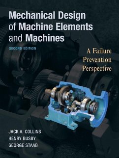
Taking a failure prevention perspective, this book provides engineers with a balance between analysis and design. The new edition presents a more thorough treatment of stress analysis and fatigue. It integrates the use of computer tools to provide a more current view of the field. Photos or images are included next to descriptions of the types and uses of common materials. The book has been updated with the most comprehensive coverage of possible failure modes and how to design with each in mind. Engineers will also benefit from the consistent approach to problem solving that will help them apply the material on the job.…mehr
Andere Kunden interessierten sich auch für
![Machine Analysis with Computer Applications for Mechanical Engineers Machine Analysis with Computer Applications for Mechanical Engineers]() James DoaneMachine Analysis with Computer Applications for Mechanical Engineers109,99 €
James DoaneMachine Analysis with Computer Applications for Mechanical Engineers109,99 €![Finite Elements Finite Elements]() A. J. BakerFinite Elements130,99 €
A. J. BakerFinite Elements130,99 €![Multidisciplinary Design Optimization in Computational Mechanics Multidisciplinary Design Optimization in Computational Mechanics]() Piotr BreitkopfMultidisciplinary Design Optimization in Computational Mechanics278,99 €
Piotr BreitkopfMultidisciplinary Design Optimization in Computational Mechanics278,99 €![Mechanical Engineering Education Mechanical Engineering Education]() Mechanical Engineering Education186,99 €
Mechanical Engineering Education186,99 €![Analysis, Design and Optimization of Composite Structures Analysis, Design and Optimization of Composite Structures]() Alexander L. KalamkarovAnalysis, Design and Optimization of Composite Structures365,99 €
Alexander L. KalamkarovAnalysis, Design and Optimization of Composite Structures365,99 €![Handbook of Asynchronous Machines with Variable Speed Handbook of Asynchronous Machines with Variable Speed]() Hubert RazikHandbook of Asynchronous Machines with Variable Speed262,99 €
Hubert RazikHandbook of Asynchronous Machines with Variable Speed262,99 €![Handbook of Compliant Mechanisms Handbook of Compliant Mechanisms]() Handbook of Compliant Mechanisms149,99 €
Handbook of Compliant Mechanisms149,99 €-
-
-
Taking a failure prevention perspective, this book provides engineers with a balance between analysis and design. The new edition presents a more thorough treatment of stress analysis and fatigue. It integrates the use of computer tools to provide a more current view of the field. Photos or images are included next to descriptions of the types and uses of common materials. The book has been updated with the most comprehensive coverage of possible failure modes and how to design with each in mind. Engineers will also benefit from the consistent approach to problem solving that will help them apply the material on the job.
Hinweis: Dieser Artikel kann nur an eine deutsche Lieferadresse ausgeliefert werden.
Hinweis: Dieser Artikel kann nur an eine deutsche Lieferadresse ausgeliefert werden.
Produktdetails
- Produktdetails
- Verlag: Wiley & Sons
- 2. Aufl.
- Seitenzahl: 912
- Erscheinungstermin: 1. Oktober 2009
- Englisch
- Abmessung: 262mm x 215mm x 38mm
- Gewicht: 893g
- ISBN-13: 9780470413036
- ISBN-10: 0470413034
- Artikelnr.: 26607038
- Herstellerkennzeichnung
- Libri GmbH
- Europaallee 1
- 36244 Bad Hersfeld
- gpsr@libri.de
Jack A. Collins is the author of Mechanical Design of Machine Elements and Machines: A Failure Prevention Perspective, 2nd Edition, published by Wiley. Henry R. Busby is the author of Mechanical Design of Machine Elements and Machines: A Failure Prevention Perspective, 2nd Edition, published by Wiley.
Part One: Engineering Principles.
Chapter 1: Keystones of Design: Materials Selection and Geometry
Determination.
1.1 Some Background Philosophy.
1.2 The Product Design Team.
1.3 Function and Form; Aesthetics and Ergonomics.
1.4 Concepts and Definition of Mechanical Design.
1.5 Design Safety Factor.
1.6 Stages of Design.
1.7 Steps in the Design Process.
1.8 Fail Safe and Safe Life Design Concepts.
1.9 The Virtues of Simplicity.
1.10 Lessons Learned Strategy.
1.11 Machine Elements, Subassemblies, and the Whole Machine.
1.12 The Role of Codes and standards in the Design Process.
1.13 Ethics in Engineering Design.
1.14 Units.
Chapter 2: The Failure Perspective.
2.1 Role of Failure Prevention Analysis in Mechanical Design.
2.2 Failure Criteria.
2.3 Modes of Mechanical Failure.
2.4 Elastic Deformation, Yielding, and Ductile Rupture.
2.5 Elastic Instability and Buckling.
2.6 Shock and Impact.
2.7 Creep and Stress Rupture.
2.8 Wear and Corrosion.
2.9 Fretting, Fretting Fatigue, and Fretting Wear.
2.10 Failure Data and the Design Task.
2.11 Failure Assessment and Retrospective Design.
2.12 The Role of Safety Factors: Reliability Concepts.
2.13. Selection and Use of a Design Safety Factor.
2.14 Determination of Existing Safety Factors in a Completed Design: A
Conceptual Constrast.
2.15 Reliability: Concepts, Definitions, and Data.
2.16 The Dilemma of Reliability Specification versus Design Safety Factor.
Chapter 3: Materials Selection.
3.1 Steps in Materials Selection.
3.2 Analyzing Requirements of the Application.
3.3 Assembling Lists of Responsive Materials.
3.4 Matching Responsive Materials to Application Requirements;
Rank-Ordered-Data Table Method.
3.5 Matching Responsive Materials to Application Requirements; Ashby chart
Method.
Chapter 4: Response of Machine Elements to Loads and Environments; Stress,
Stain, and Energy Parameters.
4.1 Loads and Geometry.
4.2 Equilibrium Concepts and Free-Body Diagrams.
4.3 Force Analysis.
4.4 Stress Analysis; Common Stress Patterns for Common Types of Loading.
4.5 Deflection Analysis Common Types of Loading.
4.6 Stresses Caused by Curved Surfaces in Contact.
4.7 Load Sharing in Redundant Assemblies and Structures.
4.8 Preloading Concepts.
4.9 Residual Stresses.
4.10 Environmental Effects.
Chapter 5: Failure Theories.
5.1 Preliminary Discussions.
5.2 Multiaxial States of Stress and Stain.
5.3 Stress Concentration.
5.4 Combined Stress Theories of Failure.
5.5 Brittle Facture and Crack Propagation; Linear Elastic Facture
Mechanics.
5.6 Fluctuating Loads, Cumulative Damage, and Fatigue Life.
5.7 Multiaxial States of Cyclic Stress and Multiaxial Fatigue Failure
Theories.
Chapter 6: Geometry Determination.
6.1 The Contrast in Objectives Between Analysis and Design.
6.2 Basic Principles and Guidelines for Creating Shape and Size.
6.3 Critical Sections and Critical Points.
6.4 Transforming Combined Stress Failure Theories into Combined Stress
Design Equations.
6.5 Simplifying Assumptions: The Need and the Risk.
6.6 Iteration Revisited.
6.7 Fits, Tolerances, and Finishes.
Chapter 7: Design-Stage Integration of Manufacturing and Maintenance
Requirements.
7.1 Concurrent Engineering.
7.2 Design for Function, Performances, and Reliability.
7.3 Selection of the Manufacturing Process.
7.4 Design for Manufacturing (DFM).
7.5 Design for Assembly (DFA).
7.6 Design for Critical Point Accessibility, Inspectability, Disassembly,
Maintenance, and Recycling.
Part Two: Design Applications.
Chapter 8:Power Transmission Shafting; Couplings, Keys, and Splines.
8.1 Uses and Characteristics of Shafting.
8.2 Potential Failure Modes.
8.3 Shaft Materials.
8.4 Design Equations-Strength Based.
8.5 Design Equations-Deflection Based.
8.6 Shaft Vibration and Critical Speed.
8.7 Summary of Suggested Shaft Design Procedure; General Guidelines for
Shaft Design.
8.8 Couplings, Keys, and Splines.
Chapter 9: Pressurized Cylinders; Interference Fits.
9.1 Uses and Characteristics of Pressurized Cylinders.
9.2 Interference Fit Applications.
9.3 Potential Failure Modes.
9.4 Materials for Pressure Vessels.
9.5 Principles from Elasticity Theory.
9.6 Thin-Walled Cylinders.
9.7 Thick-Walled Cylinders.
9.8 Interference Fits: Pressure and Stress.
9.9 Design for Proper Interference.
Chapter 10: Plain Bearings and Lubrication.
10.1 Types of Bearings.
10.2 Uses and Characteristics of Plain Bearings.
10.3 Potential Failure Modes.
10.4 Plain Bearing Materials.
10.5 Lubrication Concepts.
10.6 Boundary-Lubricated Bearing Design.
10.7 Hydrodynamic Bearing Design.
10.8 Hydrostatic Bearing Design.
Chapter 11: Rolling Element Bearings.
11.1 Uses and Characteristics of Rolling Element Bearings.
11.2 Types of Rolling Element Bearings.
11.3 Potential Failure Modes.
11.4 Bearing Materials.
11.5 Bearing Selection.
11.6 Preloading and Bearing Stiffness.
11.7 Bearing Mounting and Enclosure.
Chapter 12: Power Screw Assemblies.
12.1 Uses and Characteristics of Power Screws.
12.2 Potential Failure Modes.
12.3 Materials.
12.4 Power Screw Torque and Efficiency.
12.5 Suggested Power Screw Design Procedure.
12.6 Critical Points and Thread Stresses.
Chapter 13: Machine Joints and Fastening Methods.
13.1 Uses and Characteristics of Joints in Machine Assemblies.
13.2 Selection of Joint Type and Fastening Method.
13.3 Potential Failure Modes.
13.4 Threaded Fasteners.
13. 5 Rivets.
13.6 Welds.
13.7 Adhesive Bonding.
Chapter 14: Springs.
14.1 Uses and Characteristics of Springs.
14.2 Types of Springs.
14.3 Potential Failure Modes.
14.5 Axially Loaded Helical-Coil Springs; Stress, Deflection, and Spring
Rate.
14.6 Summary of Suggested Helical-Coil Spring Design Procedure, and General
Guidelines for Spring Design.
14.7 Beam Springs (Leaf Springs).
14.8 Summary of Suggested Leaf Spring Design Procedure.
14.9 Torsion Bars and Other Torsion Springs.
14.10 Belleville (Coned-Disk) Springs.
14.11 Energy Storage in Springs.
Chapter 15: Gears and Systems of Gears.
15.1 Uses and Characteristics of Gears.
15.2 Types of Gears; Factors in Selection.
15.3 Gear Trains; Reduction Ratios.
15.4 Potential failure Modes.
15.5 Gear Materials.
15.6 Spur Gears; Tooth Profile and Mesh Geometry.
15.7 Gear Manufacturing; Methods, Quality, and Cost.
15.8 Spur Gears; Force Analysis.
15.9 Spur Gears; Stress Analysis and Design.
15.10 Lubrication and Heat Dissipation.
15.11 Spur Gears; Summary of Suggested Design Procedure.
15.12 Helical Gears; Nomenclature, Tooth Geometry, and Mesh Interaction.
15.13 Helical Gears; Force Analysis.
15.14 Helical Gears; Stress Analysis and Design.
15.15 Helical Gears; Summary of Suggested Design Procedure.
15.16 Bevel Gears; Nomenclature, Tooth Geometry, and Mesh Interaction.
15.17 Bevel Gears; Force Analysis.
15.18 Bevel Gears; Stress Analysis and Design.
15.19 Bevel Gears; Summary of Suggested Design Procedure.
15.20 Worm Gears and Worms; Nomenclature, Tooth Geometry, and Mesh
Interaction.
15.21 Worm Gears and Worms; Force Analysis and Efficiency.
15.22 Worm Gears and Worms; Stress Analysis and Design.
15.23 Worm Gears and Worms; Suggested Design Procedure.
Chapter 16: Brakes and Clutches.
16.1 Uses and Characteristics of Brakes and Clutches.
16.2 Types of Brakes and Clutches.
16.3 Potential Failure Modes.
16.4 Brake and Clutch Materials.
16.5 Basic Concepts for Design of Brakes and Clutches.
16.6 Rim (Drum) Brakes with Short Shoes.
16.7 Rim (Drum) Brakes with Long Shoes.
16.8 Band Brakes.
16.9 Disk Brakes and Clutches.
16.10 Cone Clutches and Brakes.
Chapter 17: Belts, Chains, Wire Rope, and Flexible Shafts.
17.1 Uses and Characteristics of Flexible Power Transmission Elements.
17.2 Belt Drives; Potential Failure Modes.
17.3 Belts; Materials.
17.4 Belt Drives; Flat Belts.
17.5 Belt Drives: V-Belts.
17.6 Belt Drives; Synchronous Belts.
17.7 Chain Drives; Potential Failure Modes.
17.8 Chain Drives; Materials.
17.9 Chain Drives; Precision Roller Chain.
17.10 Roller Chain Drives; Suggested Selection Procedure.
17.11 Chain Drives; Inverted-Tooth Chain.
17.12. Wire Rope; Potential Failure Modes.
17.13 Wire Rope; Materials.
17.14 Wire Rope; Stresses and Strains.
17.15 Wire Rope; Suggested Selection Procedure.
17.16 Flexible Shafts.
Chapter 18: Flywheels and High-Speed Rotors.
18.1 Uses and Characteristics of Flywheels.
18.2 Fluctuating Duty Cycles, Energy Management, and Flywheel inertia.
18.3 Types of Flywheels.
18.4 Potential Failure Modes.
18.5 Flywheel Materials.
18.6 Spoke-and-Rim Flywheels.
18.7 Disk Flywheels of Constant Thickness.
18.8 Disk Flywheels of Uniform Strength.
18.9 Uniform-Strength Disk Flywheel with a Rim.
18.10 Flywheels-to-Shaft Connections.
Chapter 19: Cranks and Crankshafts.
19.1 Uses and Characteristics of Crankshafts.
19.2 Types of Crankshafts.
19.3 Potential Failure Modes.
19.4 Crankshaft Materials.
19.5 Summary of Suggested Crankshaft Design Procedure.
Chapter 20: Completing the Machine.
20.1 Integrating the Components; Bases, Frames, and Housings.
20.2 Safety Issues; Guards, Devices, and Warnings.
20.3 Design Reviews; Releasing the Final Design.
Appendix: NSPE Code of Ethics for Engineers.
Table A-1 : Coefficients of Friction.
Table A-2: Mass Moments of Inertia J and Radii of Gyration k for Selected
Homogeneous Solid Bodies Rotating About Selected Axes, as Sketched.
Table A-3: Section Properties of Selected W (Wide Flange) Shapes.
Table A-4: Section Properties of Selected S (Standard 1) Shapes.
Table A-5: Section Properties of Selected C (Channel) Shapes.
Table A-6: Section Properties of Selected Equal-Leg L (Angle) Shapes.
References.
Photo Credits.
Index.

