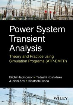
Eiichi Haginomori, Tadashi Koshiduka, Junichi Arai, Hisatochi Ikeda
Power System Transient Analysis
Theory and Practice Using Simulation Programs (Atp-Emtp)
Eiichi Haginomori, Tadashi Koshiduka, Junichi Arai, Hisatochi Ikeda
Power System Transient Analysis
Theory and Practice Using Simulation Programs (Atp-Emtp)
- Gebundenes Buch
- Merkliste
- Auf die Merkliste
- Bewerten Bewerten
- Teilen
- Produkt teilen
- Produkterinnerung
- Produkterinnerung
Understanding transient phenomena in electric power systems and the harmful impact of resulting disturbances is an important aspect of power system operation and resilience. Bridging the gap from theory to practice, this guide introduces the fundamentals of transient phenomena affecting electric power systems using the numerical analysis tools, Alternative Transients Program- Electromagnetic Transients Program (ATP-EMTP) and ATP-DRAW. This technology is widely-applied to recognize and solve transient problems in power networks and components giving readers a highly practical and relevant…mehr
Andere Kunden interessierten sich auch für
![Wavelet Analysis and Transient Signal Processing Applications for Power Systems Wavelet Analysis and Transient Signal Processing Applications for Power Systems]() Zhengyou HeWavelet Analysis and Transient Signal Processing Applications for Power Systems152,99 €
Zhengyou HeWavelet Analysis and Transient Signal Processing Applications for Power Systems152,99 €![Transient Analysis of Power Systems Transient Analysis of Power Systems]() Transient Analysis of Power Systems182,99 €
Transient Analysis of Power Systems182,99 €![Transient Characteristics, Modelling and Stability Analysis of Microgrid Transient Characteristics, Modelling and Stability Analysis of Microgrid]() Zhikang ShuaiTransient Characteristics, Modelling and Stability Analysis of Microgrid77,99 €
Zhikang ShuaiTransient Characteristics, Modelling and Stability Analysis of Microgrid77,99 €![Electromagnetic Transient Analysis and Novel Protective Relaying Techniques for Power Transformers Electromagnetic Transient Analysis and Novel Protective Relaying Techniques for Power Transformers]() Xiangning LinElectromagnetic Transient Analysis and Novel Protective Relaying Techniques for Power Transformers182,99 €
Xiangning LinElectromagnetic Transient Analysis and Novel Protective Relaying Techniques for Power Transformers182,99 €![Transient Analysis of Electric Power Circuits Handbook Transient Analysis of Electric Power Circuits Handbook]() Arieh L. ShenkmanTransient Analysis of Electric Power Circuits Handbook149,99 €
Arieh L. ShenkmanTransient Analysis of Electric Power Circuits Handbook149,99 €![Transient Analysis of Electric Power Circuits Handbook Transient Analysis of Electric Power Circuits Handbook]() Arieh L. ShenkmanTransient Analysis of Electric Power Circuits Handbook237,99 €
Arieh L. ShenkmanTransient Analysis of Electric Power Circuits Handbook237,99 €![Parallel Large-Scale Power System Electromagnetic Transient Simulation Parallel Large-Scale Power System Electromagnetic Transient Simulation]() Zhiyin ZhouParallel Large-Scale Power System Electromagnetic Transient Simulation32,99 €
Zhiyin ZhouParallel Large-Scale Power System Electromagnetic Transient Simulation32,99 €-
-
-
Understanding transient phenomena in electric power systems and the harmful impact of resulting disturbances is an important aspect of power system operation and resilience. Bridging the gap from theory to practice, this guide introduces the fundamentals of transient phenomena affecting electric power systems using the numerical analysis tools, Alternative Transients Program- Electromagnetic Transients Program (ATP-EMTP) and ATP-DRAW. This technology is widely-applied to recognize and solve transient problems in power networks and components giving readers a highly practical and relevant perspective and the skills to analyse new transient phenomena encountered in the field. Key features: * Introduces novice engineers to transient phenomena using commonplace tools and models as well as background theory to link theory to practice. * Develops analysis skills using the ATP-EMTP program, which is widely used in the electric power industry. * Comprehensive coverage of recent developments such as HVDC power electronics with several case studies and their practical results. * Provides extensive practical examples with over 150 data files for analysing transient phenomena and real life practical examples via a companion website. Written by experts with deep experience in research, teaching and industry, this text defines transient phenomena in an electric power system and introduces a professional transient analysis tool with real examples to novice engineers in the electric power system industry. It also offers instruction for graduates studying all aspects of power systems.
Hinweis: Dieser Artikel kann nur an eine deutsche Lieferadresse ausgeliefert werden.
Hinweis: Dieser Artikel kann nur an eine deutsche Lieferadresse ausgeliefert werden.
Produktdetails
- Produktdetails
- Verlag: John Wiley & Sons / Wiley
- Seitenzahl: 280
- Erscheinungstermin: 2. Mai 2016
- Englisch
- Abmessung: 251mm x 164mm x 20mm
- Gewicht: 573g
- ISBN-13: 9781118737538
- ISBN-10: 1118737539
- Artikelnr.: 43370709
- Herstellerkennzeichnung
- Libri GmbH
- Europaallee 1
- 36244 Bad Hersfeld
- gpsr@libri.de
Eiichi Haginomori, University of Tokyo, Japan Eiichi Haginomori is currently at the University of Tokyo. Previous to this he was in the Department of Electrical Engineering at Kyushu Institute of Technology (1998-2003) and in Chemical Engineering at Chuo University. At both universities he researched into EMTP application to Electrical Engineering. He was Chief Specialist in the Switchgear Engineering Department of Toshiba's Head Office for ten years, and belongs to IEC standard committee groups such as WG1 and WG10, in IEC SC17A (High-voltage Switchgear and controlgear). Tadashi Koshiduka, Toshiba Co., Japan Tadashi Koshizuka is currently a Senior Scientist at the High Power Technology Group in the Power & Industrial Systems Research & Development Center at Toshiba, Japan. Prior to this he worked as an engineer with the group (1998-2000), then a specialist (2000-2010). He is a technical paper reviewer in the Power and Energy Society of IEE Japan and current member and secretary of IEEDJ (The Institute of Engineers on Electrical Discharges in Japan). Mr Koshizuka holds three Japanese Patents, has contributed to 17 papers and co-authored one book. Junichi Arai, Kougakuin University, Japan Professor Arai is Chair of the Department of Electrical Engineering and Dean of the Faculty of Engineering at Kogakuin University. Previous to this he was Senior Fellow of the Transmission & Distribution System Division at Toshiba Corp., and Deputy Senior Chief Engineer in the International Marketing Division of TM T&D Corp. He has written seventeen papers related to the topic, a chapter in Electrical Engineering Handbook, published by IEE of Japan, and a chapter in Liberalization of Electricity Markets and Technological Issues. He holds 10 patents related to his research in power control and circuits. Hisatoshi Ikeda, University of Tokyo, Japan Hisatoshi Ikeda is currently Project Professor, having been Visiting Professor at Kyushu Institute of Technology for three years previously. From 2002 to 2007 he was General Manager, Transmission and Distribution Research and Development Center at TM T&D Co, andAssistant General Manager at Hamakawasaki-works, Toshiba Corp. Professor Ikeda holds 56 Japanese patents and 12 USA patents. He has been a secretary of the short-circuit testing liaison in Japan.
Preface ix Part I Standard Course-Fundamentals and Typical Phenomena 1 1 Fundamentals of EMTP 3 1.1 Function and Composition of EMTP 3 1.1.1 Lumped Parameter RLC 3 1.1.2 Transmission Line 4 1.1.3 Transformer 6 1.1.4 Nonlinear Element 6 1.1.5 Arrester 6 1.1.6 Switch 7 1.1.7 Voltage and Current Sources 7 1.1.8 Generator and Rotating Machine 7 1.1.9 Control 7 1.1.10 Support Routines 7 1.2 Features of the Calculation Method 8 1.2.1 Formulation of the Main Circuit 8 1.2.2 Calculation in TACS 12 1.2.3 Features of EMTP 13 References 16 2 Modeling of System Components 17 2.1 Overhead Transmission Lines and Underground Cables 17 2.1.1 Overhead Transmission Line-Line Constants 17 2.1.2 Underground Cables-Cable Parameters 37 2.2 Transformer 46 2.2.1 Single
Phase Two-Winding Transformer 46 2.2.2 Single
Phase Three
Winding Transformer 50 2.2.3 Three
Phase One
Core Transformer-Three Legs or Five Legs 53 2.2.4 Frequency and Transformer Modeling 55 3 Transient Currents in Power Systems 57 3.1 Short
Circuit Currents 57 3.2 Transformer Inrush Magnetizing Current 60 3.3 Transient Inrush Currents in Capacitive Circuits 62 Appendix 3.A: Example of ATPDraw Sheets-Data3
02.acp 64 Reference 64 4 Transient at Current Breaking 65 4.1 Short
Circuit Current Breakings 66 4.2 Capacitive Current Switching 71 4.2.1 Switching of Capacitive Current of a NöLoad Overhead Transmission Line 72 4.2.2 Switching of Capacitive Current of a Cable 75 4.2.3 Switching of Capacitive Current of a Shunt Capacitor Bank 76 4.3 Inductive Current Switching 78 4.3.1 Current Chopping Phenomenon 78 4.3.2 Reignition 79 4.3.3 High
Frequency Extinction and Multiple Reignition 80 4.4 TRV with Parallel Capacitance in SLF Breaking 80 Appendix 4.A: Current Injection to Various Circuit Elements 84 Appendix 4.B: TRV Calculation, Including ITRV-Current Injection is Applied for TRV Calculation 91 Appendix 4.C: 550 kV Line Normal Breaking 97 Appendix 4.D: 300 kV, 150 MVA Shunt Reactor Current Breaking-Current Chopping-Reignition-HF Current Interruption 100 References 103 5 Black Box Arc Modeling 105 5.1 Mayr Arc Model 106 5.1.1 Analysis of Phenomenon of Short
Line Fault Breaking 106 5.1.2 Analysis of Phenomenon of Shunt Reactor Switching 110 5.2 Cassie Arc Model 112 5.2.1 Analysis of Phenomenon of Current Zero Skipping 113 Appendix 5.A: Mayr Arc Model Calculating SLF Breaking, 300 kV, 50 kA, L90 Condition 118 Appendix 5.B: Zero Skipping Current Breaking Near Generator-Fault Current Lasting 124 Appendix 5.C: Zero Skipping Current Breaking Near Generator-Dynamic Arc Introduced, Still Nonbreaking 131 6 Typical Power Electronics Circuits in Power Systems 135 6.1 General 135 6.2 HVDC Converter/Inverter Circuits 135 6.3 Static Var Compensator/Thyristor
Controlled Inductor 140 6.4 PWM Self
Communicated Type Inverter Applying the Triangular Carrier Wave Shape Principle-Applied to SVG (Static Var Generator) 142 Appendix 6.A: Example of ATPDraw Picture 147 Reference 148 Part II Advanced Course-Special Phenomena and Various Applications 149 7 Special Switching 151 7.1 Transformer
Limited Short
Circuit Current Breaking 151 7.2 Transformer Winding Response to Very Fast Transient Voltage 152 7.3 Transformer Magnetizing Current under Geomagnetic Storm Conditions 156 7.4 Four
Armed Shunt Reactor for Suppressing Secondary Arc in Single
Pole Rapid Reclosing 159 7.5 Switching Four
Armed Shunt Reactor Compensated Transmission Line 162 References 163 8 Synchronous Machine Dynamics 165 8.1 Synchronous Machine Modeling and Machine Parameters 165 8.2 Some Basic Examples 167 8.2.1 NöLoad Transmission Line Charging 167 8.2.2 Power Flow Calculation 169 8.2.3 Sudden Short
Circuiting 172 8.3 Transient Stability Analysis Applying the Synchronous Machine Model 176 8.3.1 Classic Analysis (Equal
Area Method) and Time Domain Analysis (EMTP) 176 8.3.2 Detailed Transients by Time Domain Analysis: ATP
EMTP 180 8.3.3 Field Excitation Control 183 8.3.4 Back
Swing Phenomenon 186 Appendix 8.A: Short
Circuit Phenomena Observation in d
q Domain Coordinate 190 Appendix 8.B: Starting as an Induction Motor 193 Appendix 8.C: Modeling by the No. 19 Universal Machine 195 Appendix 8.D: Example of ATPDraw Picture File: Draw8
111.acp (Figure D8.1). 197 References 198 9 Induction Machine, Doubly Fed Machine, Permanent Magnet Machine 199 9.1 Induction Machine (Cage Rotor Type) 199 9.1.1 Machine Data for EMTP Calculation 200 9.1.2 Zero Starting 201 9.1.3 Mechanical Torque Load Application 204 9.1.4 Multimachines 206 9.1.5 Motor Terminal Voltage Change 208 9.1.6 Driving by Variable Voltage and Frequency Source (VVVF) 209 9.2 Doubly Fed Machine 212 9.2.1 Operation Principle 212 9.2.2 Steady
State Calculation 213 9.2.3 Flywheel Generator Operation 213 9.3 Permanent Magnet Machine 215 9.3.1 Zero Starting (Starting by Direct AC Voltage Source Connection) 217 9.3.2 Calculation of Transient Phenomena 217 Appendix 9.A: Doubly Fed Machine Vector Diagrams 218 Appendix 9.B: Example of ATPDraw Picture 219 10 Machine Drive Applications 221 10.1 Small
Scale System Composed of a Synchronous Generator and Induction Motor 221 10.1.1 Initialization 221 10.1.2 Induction Motor Starting 223 10.1.3 Application of AVR 225 10.1.4 Inverter
Controlled VVVF Starting 226 10.2 Cycloconverter 233 10.3 Cycloconverter
Driven Synchronous Machine 237 10.3.1 Application of Sudden Mechanical Load 237 10.3.2 Quick Starting of a Cycloconverter
Driven Synchronous Motor 242 10.3.3 Comparison with the Inverter
Driven System 245 10.4 Flywheel Generator: Doubly Fed Machine Application for Transient Stability Enhancement 248 10.4.1 Initialization 249 10.4.2 Flywheel Activity in Transient Stability Enhancement 254 10.4.3 Active/Reactive Power Effect 254 10.4.4 Discussion 258 Appendix 10.A: Example of ATPDraw Picture 260 Reference 266 Index 267

