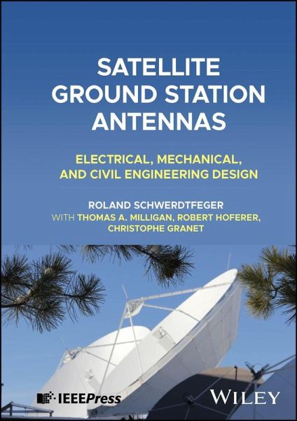
Roland Schwerdtfeger, Thomas A Milligan, Robert Hoferer, Christophe Granet
Satellite Ground Station Antennas
Electrical, Mechanical, and Civil Engineering Design
Roland Schwerdtfeger, Thomas A Milligan, Robert Hoferer, Christophe Granet
Satellite Ground Station Antennas
Electrical, Mechanical, and Civil Engineering Design
- Gebundenes Buch
- Merkliste
- Auf die Merkliste
- Bewerten Bewerten
- Teilen
- Produkt teilen
- Produkterinnerung
- Produkterinnerung
Understand all aspects of ground station design with this groundbreaking volume A satellite ground station is a terrestrial station built to communicate or receive signals from spacecraft and other astronomical and interplanetary sources. Since ground stations are subject to weather and other terrestrial conditions, their operations can be unpredictable, and their design offers numerous challenges for engineers. Satellite Ground Station Antennas constitutes the first-ever comprehensive overview of these challenges and the tools by which engineers of all kinds can meet them. Analyzing every…mehr
Andere Kunden interessierten sich auch für
- Bruce R. ElbertThe Satellite Communication Ground Segment and Earth Station Handbook176,99 €
- Shkelzen CakajGround Station Design and Analysis for Leo Satellites140,99 €
- Mohamed Slim Ben MahmoudAeronautical Air-Ground Data Link Communications191,99 €
- Guolong HeMultibeam Phased Array Antennas as Satellite Constellation Ground Station59,99 €
- Guolong HeMultibeam Phased Array Antennas as Satellite Constellation Ground Station81,99 €
- Z. WuRadiowave Propagation Over Ground Software373,99 €
- Debatosh GuhaDefected Ground Structure (Dgs) Based Antennas149,99 €
-
-
-
Understand all aspects of ground station design with this groundbreaking volume A satellite ground station is a terrestrial station built to communicate or receive signals from spacecraft and other astronomical and interplanetary sources. Since ground stations are subject to weather and other terrestrial conditions, their operations can be unpredictable, and their design offers numerous challenges for engineers. Satellite Ground Station Antennas constitutes the first-ever comprehensive overview of these challenges and the tools by which engineers of all kinds can meet them. Analyzing every aspect of ground station antenna technology, the book can be read both continuously or as a reference, with each chapter functioning by itself to fully apprehend a discrete portion of the subject. Balancing mathematics with mechanics, it combines accessibility and rigor to create an unprecedented resource. Readers will also find: * In-depth material published in a fully accessible form for the first time * Detailed discussion of topics including reflector design, structural considerations, proof-of-performance, and more * Lavish illustrations and photographs throughout Satellite Ground Station Antennas is ideal for electrical, mechanical, and civil engineers, as well as for any other industry professional working with ground station design.
Hinweis: Dieser Artikel kann nur an eine deutsche Lieferadresse ausgeliefert werden.
Produktdetails
- Produktdetails
- Verlag: Wiley
- Seitenzahl: 464
- Erscheinungstermin: 15. Januar 2025
- Englisch
- Gewicht: 666g
- ISBN-13: 9781394191710
- ISBN-10: 1394191715
- Artikelnr.: 67435834
- Herstellerkennzeichnung
- Libri GmbH
- Europaallee 1
- 36244 Bad Hersfeld
- 06621 890
- Verlag: Wiley
- Seitenzahl: 464
- Erscheinungstermin: 15. Januar 2025
- Englisch
- Gewicht: 666g
- ISBN-13: 9781394191710
- ISBN-10: 1394191715
- Artikelnr.: 67435834
- Herstellerkennzeichnung
- Libri GmbH
- Europaallee 1
- 36244 Bad Hersfeld
- 06621 890
Roland Schwerdtfeger was a Life Member of the IEEE with decades of experience in ground station design and operation, achieving global recognition as the definitive expert. Thomas A. Milligan has served as Principal Engineer for numerous advanced antenna design projects and NASA planetary probes. He is an IEEE Life Fellow and former longtime editor of the "Antenna Designer's Notebook" column in the IEEE Antenna Magazine. Robert Hoferer, PhD, has 30 years' experience in antenna feed systems and reflector antennas for satellite communication. A Senior Member of the IEEE, he has served since 2013 as co-founder and Chief Technology Officer for Spacetime Engineering. Christophe Granet, PhD, is an award-winning antenna engineer with over 30 years' experience, and founder of Lyrebird Antenna Research Ltd. He is a Senior Member of the IEEE and in 2001 received the H.A. Wheeler Award from the IEEE Antennas and Propagation Society.
About the Authors xix Preface xxi Acknowledgments xxiii Glossary of Terms xxv Introduction xxxi 1 Antenna System Analysis 1 1.1 Introduction 1 1.2 Antenna Radiation and Path Loss 1 1.3 Polarization 3 1.3.1 Polarization Efficiency 4 1.4 Geometry of Satellite Communication Link 5 1.4.1 Pointing Angles to Satellites 5 1.4.1.1 The Case for the Elevation-over-Azimuth Antenna 5 1.4.1.2 The Case for the Declination-over-Hour Angle Antenna 8 1.4.2 Elevation-over-Azimuth Pattern Angle Correction 10 1.4.3 Sun Outage 10 1.4.4 Linear Polarization Twist at Ground Station from Satellite 11 1.5 Noise in Antennas 12 1.5.1 Noise Mechanisms 12 1.5.2 Signal-to-Noise Ratio 13 1.5.3 Noise Power 13 1.5.4 Equivalent Noise Temperature 14 1.5.5 Noise Figure 14 1.5.6 Antenna Noise Temperature 16 1.5.7 Noise in a Satellite-Earth Station Link 17 1.5.8 Antenna Noise Temperature Components 18 1.5.8.1 Sky Noise 18 1.5.8.2 Antenna Noise Temperature 21 1.5.9 Sky Noise Temperature Variation with Ambient Temperature and Humidity 25 1.6 Interference in Antennas 29 1.6.1 Introduction 29 1.6.1.1 Sources of Interference 30 1.6.1.2 Corrective Filter Application 30 1.6.2 Interference by the Transmitter 31 1.6.3 Interference by Tx Signal Power 33 1.6.4 Interference due to Tx Noise Power 35 1.7 Passive Intermodulation in Antennas 39 1.7.1 Brief History 39 1.7.2 Theory 39 1.7.2.1 Second-Order PIM - Two Equal Amplitude Transmit Carriers 40 1.7.2.2 Third-Order PIM - Two Equal Amplitude Transmit Carriers 40 1.7.2.3 Third-Order PIM - Three Equal Amplitude Transmit Carriers 40 1.7.2.4 Specific Cases of PIM Frequencies 41 1.7.2.5 Amplitude of PIMs 41 1.7.2.6 Causes of PIM in Antennas 45 1.7.3 Some Interesting Observations 46 1.7.3.1 Measurement of PIMs 47 1.8 Link Analysis 47 1.8.1 Uplink Analysis 47 1.8.2 Downlink Analysis 50 1.8.3 EIRP and Power Density 52 1.9 Digital Communication Link Budget 54 1.9.1 Link Budget Supplied by Marc R. Björkman for Commercial Satellite Multichannel TV Transmission 54 References 55 2 Reflector Design 57 2.1 Introduction 57 2.2 Single Reflector Antenna 59 2.2.1 Prime Focus Antenna Efficiency Components 60 2.2.1.1 Phase Error Loss 61 2.2.1.2 Illumination Loss 62 2.2.1.3 Spillover Loss 63 2.2.1.4 Blockage 63 2.2.1.5 Polarization Loss 64 2.2.1.6 Reflector Panel Loss 64 2.2.1.7 Reflection Loss 64 2.2.1.8 Feed Terminal Losses 64 2.2.1.9 Summary 64 2.2.2 General Performance Features 65 2.3 Two-Reflector Design 65 2.3.1 Cassegrain and Gregorian Configurations 65 2.3.2 Antenna Efficiency Components 68 2.3.2.1 Subreflector Blockage 68 2.3.2.2 Subreflector Support Structure Blockage 68 2.3.2.3 Feed Blockage 68 2.3.2.4 Diffraction Loss 70 2.3.2.5 General Performance Features 70 2.3.3 Shaped Reflector Design Considerations 71 2.3.3.1 General Performance Features of the Shaped System 77 2.3.4 The Ring Focus Antenna 78 2.3.4.1 Positive Features of Ring Focus 78 2.3.4.2 Negative Features of the Ring Focus 78 2.3.4.3 General Performance Features 79 2.4 Offset Reflector Antennas 80 2.4.1 Single Offset Reflector Antenna 80 2.4.1.1 Cross-pol Matched Feed System for Single Offset Reflector Applications 87 2.4.2 Horn Reflector 87 2.4.3 Dual-Offset Antennas - Cassegrain and Gregorian 92 2.4.4 Dragonian Reflector System 97 2.5 Characteristics of Antenna Patterns 97 2.5.1 Concept of Antenna Pattern Gain 102 2.6 Antennas with Simultaneous Multiband Feeds 105 2.6.1 Single Aperture Feed Horn 105 2.6.2 Wideband Feed Horn 108 2.6.3 Concentric Aperture Feed Horns 110 2.6.4 Dual Aperture Feeds with FSS 111 2.7 Selectable Multi-feed Systems 111 2.8 Beam Waveguide 115 2.8.1 Introduction 115 2.8.2 Large Antenna Beam Waveguide 115 2.8.3 The Quasi-Beam Waveguide 122 2.9 Multibeam Antennas 123 2.9.1 Introduction 123 2.9.2 The Torus 126 2.9.2.1 The Declination Difficulty and Off-Axis Feed Settings 128 2.9.2.2 Phase Aberrations in the Feed Horn 133 2.9.2.3 Siting the Torus to Other Latitudes 133 2.9.2.4 General Performance Features of the Torus 135 2.9.3 Shaped Cassegrain CSIRO MBA Antenna 139 References 139 3 Feed System Design 141 3.1 Introduction 141 3.2 Linearly Polarized Rx Feed Design and Configurations 142 3.2.1 Example Satellite Link 142 3.2.2 Single Linear Polarization - with Polarization Rotation 146 3.2.3 Dual Linear Polarization - Receive Only 148 3.2.4 Linearly Polarized Tx/Rx Feed Design and Configurations 149 3.2.5 Linear Polarization - Two Orthogonal Rx and One Tx 151 3.2.6 Dual Linear Polarized Rx and Tx 153 3.3 Circular Polarization (CP) - Rx-Only Feed Configurations 157 3.3.1 OMT + 90
Power Divider 158 3.3.2 Differential Phase Shifter with OMT 160 3.3.3 Septum-OMT 164 3.3.4 OMT with Rectangular Horn 167 3.4 Two-Port Circularly Polarized Rx/Tx Feed Systems 168 3.4.1 Four-Port CP Feed Network 171 3.5 Polarization Rotation and Switching 173 3.5.1 90
Differential Phase Shifter - CP/LP Selection 173 3.5.2 180
Differential Phase Shifter - LP Angle Adjust Only 174 3.5.3 CP/LP and LP Angle Adjust 176 3.5.4 90
Differential Phase Shifter - CP Adjust 178 3.5.5 CP/LP Selection - Two-Port Rx/Tx Feed 178 3.6 Combined Dual-Polarized Tx/Rx Feed Configuration 179 3.6.1 Single QJ and Magic Tee Feed System Network Layout 180 3.6.2 Twin-QJ Feed System Layout 181 3.6.3 Tri-band Feed Using Twin-QJ and Symmetric OMT 181 3.6.4 Combined CP and LP Tx/Rx Feed Configuration 183 3.7 Feed System Terminal Characteristics 185 3.7.1 VSWR - Effect of Multiple Contributions 186 3.7.2 Practical Matching Techniques 187 3.7.3 Polarization Discrimination - Axial Ratio and Cross-pol 188 3.7.4 Port-to-Port Isolation 189 3.7.5 Insertion Loss 189 3.7.6 Signal Delay Time 190 References 190 4 Tracking Feed Systems 193 4.1 Introduction 193 4.2 Maximum Signal "Search and Track" Methods 195 4.2.1 Step Track 195 4.2.2 Conical Scan 196 4.2.3 Electronic Conical Scan 196 4.3 Zero-Signal Track Methods 199 4.3.1 Phase-Amplitude Monopulse 199 4.3.1.1 TM 01 + TE 01 Mode Pattern 200 4.3.1.2 TE 21 Mode Pattern 202 4.3.2 TE 21 Mode Coupler Design Concepts 202 4.3.2.1 A System Performance Study 209 4.3.2.2 Error Channel Path 212 4.4 Array Monopulse Feeds 214 4.4.1 Four-Horn "Cross" Array 214 4.4.2 Four-Horn "Corner" Array 216 4.4.3 The Integrated Five-Horn Array 216 4.4.4 Polarization Requirements for Monopulse Functions 221 4.4.5 Monopulse Detection Methods 221 4.4.6 The Impact of the Presence of a
Az Cross-Talk Signal 224 4.5 Array Analysis and Design 224 4.5.1 The Sum of the Array Elements 228 4.5.2 The Difference Between Array Element Pairs 228 4.5.2.1 The Cross Array - Figure 4.32 229 4.5.2.2 The Corner Array - Figure 4.33 229 4.5.2.3 The Five-Horn Monopulse Array 231 References 235 5 Structural and Mechanical 237 5.1 Introduction 237 5.2 Antenna Configurations 237 5.3 Antenna Axis Configurations 242 5.3.1 Elevation-over-Azimuth 242 5.3.2 X-Y or Cross-Elevation-over-Elevation 243 5.3.3 Declination-over-Hour Angle 245 5.4 Reflector Support Structures 248 5.5 Reflector Geometries 252 5.6 Reflector Accuracy 252 5.7 Design of Reflector Panels 257 5.7.1 Main Reflector Fabrication 257 5.7.1.1 Stretched Panels with "Zees" 257 5.7.1.2 Stretched Panels with Precision Profiled Radials 259 5.7.1.3 Truss Support Construction 260 5.7.1.4 Machined Panels 260 5.7.1.5 Stretched Panels with Honeycomb Core Between Two Stretched Panels 260 5.7.1.6 Metal Spinning Manufacturing 261 5.7.1.7 Fiberglass and Carbon Fiber Lay-ups 262 5.7.2 Subreflector Fabrication 263 5.8 Pointing Accuracy 264 5.8.1 Beam Deviation Factor 267 5.8.2 Beam Tilt Due to Main Reflector Translation 271 5.8.3 Beam Tilt Due to Main Reflector Rotation 271 5.8.4 Beam Tilt Due to Subreflector Translation 271 5.8.5 Beam Tilt Due to Subreflector Rotation 272 5.8.6 Beam Tilt Due to Feed Translation/Rotation 272 5.8.7 Subreflector Axial Displacement 272 5.9 Structural Alignment 274 5.9.1 Orthogonality 274 5.10 Panel Alignment 276 5.10.1 Theodolite and Precision Drill Tape Panel Setting 276 5.10.2 Laser Tracker 277 5.10.3 Photogrammetry and Precision Reference Scale 277 5.10.4 Microwave Interferometry (Holography) 277 5.11 Influences of Weather 278 5.12 Mechanical Layout Concepts for Complex Feed Systems 280 5.12.1 A Brief Summary of Important Feed Design Considerations 280 5.12.2 Sample Feed Design Problem 280 References 283 6 Antenna Protection 285 6.1 Protecting the Feed Against the Elements 285 6.1.1 Feed Horn Window Considerations 285 6.1.2 Feed Pressurization Principles 287 6.1.2.1 Example System Leak Rate Calculation 288 6.1.2.2 Leakage of Air from the Feed System 289 6.1.3 Waveguide System Dehydration 291 6.2 Feed Protection against Rain, Mist, Snow and Ice, and Birds 293 6.2.1 Rain-Blower 293 6.2.2 Feed Window Material 295 6.2.3 Hydrophobic Coatings 295 6.2.4 Bird Protection 295 6.3 Radomes 297 6.3.1 Sandwich Radomes 298 6.3.1.1 Construction 298 6.3.1.2 Geometry 298 6.3.1.3 Electromagnetic Performance 301 6.3.2 Solid Laminate Radomes 301 6.3.2.1 Construction 301 6.3.2.2 Electromagnetic Performance 302 6.3.3 Air-Supported Radomes 302 6.3.3.1 Construction 302 6.3.3.2 Electromagnetic Performance 303 6.3.4 Space Frame Radomes 303 6.3.4.1 Construction 303 6.3.4.2 Electromagnetic Performance 303 6.3.4.3 Design Aspects of Metal Space Frame Radomes 308 6.3.4.4 Results of Measurements on Antennas Under Metal, MSF, and Dielectric Space Frame, DSF, Radomes 308 6.3.4.5 Passive Intermodulation Issues in Metal Space Frame Radomes 309 6.3.4.6 Short Comparison of Metal Space Frame and Air-Inflated Radomes 309 6.3.5 Selection Criteria 309 6.3.5.1 Electromagnetic Performance 310 6.3.5.2 Maintenance and Support 311 6.3.6 Brief Summary of Radome Features 311 6.3.6.1 Reasons for Use 311 6.3.6.2 Impact on Antenna Performance by the Radome - Gain, G/T, Sidelobe Envelope 312 6.3.6.3 Comparative Radome Attributes 313 References 314 7 Site Considerations 315 7.1 Radiation Hazard 315 7.2 Earth Station Site Planning 321 7.2.1 Obstructions and Safety 321 7.2.1.1 Satellite Link Obscuration Sources 321 7.3 Antenna Site Interference Issues 323 7.3.1 Terrestrial Interference 323 7.3.2 Interfacility Links 327 7.3.3 RF Leakage 327 7.3.4 Weather 328 References 329 8 Proof-of-Performance 331 8.1 The Specification 331 8.2 Basic System Requirements 332 8.3 Factory Testing 332 8.3.1 Feed System and Performance Features 333 8.3.1.1 Feed Patterns 334 8.3.1.2 Polarization Discrimination/Isolation - Linearly Polarized Feed Configurations 334 8.3.1.3 Axial Ratio - Circularly Polarized Feed Configurations 335 8.3.1.4 Return Loss 335 8.3.1.5 Port-to-Port Isolation 335 8.3.1.6 Insertion Loss 335 8.3.1.7 Time or Group Delay 335 8.3.1.8 Passive Intermodulation 336 8.3.1.9 RF Leak 336 8.3.1.10 Mechanical Details 336 8.3.1.11 Polarization Control - Remote or Manual 336 8.3.1.12 Pressurization Leak Rate 336 8.3.1.13 Dimensional Check of Feed Assembly 336 8.3.2 Feed System - Sample Measurements 337 8.3.2.1 Return Loss Measurement 337 8.3.2.2 Insertion Loss Measurement 337 8.3.2.3 Port-to-Port Isolation Measurement 337 8.3.2.4 Polarization Discrimination (Cross-pol) Measurement 337 8.3.2.5 Pattern Measurements 338 8.3.2.6 Possible Difficulties That One Can Encounter in Feed Measurement Include 338 8.3.3 Reflector System 343 8.3.4 Effects of Reflector Errors 346 8.3.4.1 Panel Errors 346 8.3.5 Other Subsystems 348 8.3.6 Outdoor Test Range 349 8.3.6.1 Length 349 8.3.6.2 Ground Reflections 350 8.3.6.3 Advantages of Range Measurements 354 8.3.6.4 Noise Temperature Measurements 354 8.3.6.5 Summary of Range Test Activities 355 8.4 Customer Site Preparations 357 8.4.1 Pedestal Alignment Check 357 8.4.2 Reflector and Feed System Mechanical Alignment Check 357 8.4.3 Ancillary Equipment Function Check - Control System, LNAs, HPAs 358 8.4.4 IFL Signal Path Integrity 359 8.4.5 Pretest Preparations 359 8.4.5.1 Angular Range Limits for Antenna Patterns 359 8.4.5.2 Applicability of Radio Star Observations to Measure G/T and Gain 360 8.4.6 Test Equipment, Location, Setup, and Function Check 361 8.5 Preliminary RF Checks and Example Difficulties 362 8.5.1 Sum Patterns 362 8.5.2 Difference Patterns 367 8.5.3 Antenna Gain 370 8.5.4 Antenna Noise Temperature 371 8.5.5 Radio Star Track Check 372 8.5.6 IFL Signal Paths 373 8.5.6.1 Unexpected High RL (Return Loss) Values 374 8.5.6.2 Mode Spikes in RL Response 374 8.6 Formal On-Site RF Antenna Tests 376 8.6.1 Antenna Patterns - Sum, Difference, Cross-pol 376 8.6.2 Monopulse Tracking Sensitivity 376 8.6.3 Antenna Noise Temperature 376 8.6.4 Antenna System G/T, Noise Temperature, and Gain 376 8.6.4.1 Satellite Link Method 376 8.6.4.2 Beamwidth Method 376 8.6.4.3 Pattern Integration 380 8.6.4.4 Radio Star Method 380 8.6.5 Transmit Uplink Gain and EIRP Stability 384 8.7 Measurement Accuracy 384 Appendix A Appendices 385 A. 1 Feed System Insertion Loss Determination 385 A.. 1 Test Equipment Necessary for the Measurement 385 A.1. 2 Calibration of Low Noise Amplifier Against Clear Zenith Sky Temperature as Seen by a Standard Gain Horn 385 A.1. 3 Determination of the Feed System Insertion Loss 387 A. 2 Determination of Antenna Gain and G/T Using Calibrated Radio Stars 389 A.2. 1 Test Equipment 389 A.. 2 Configuring and Checking the Test Setup Prior to the Measurement 389 A.2. 3 Formal Measurement Procedure 394 A.2. 4 Data Analysis 396 A.2.4. 1 Basis for the Measurement Method 396 A..4. 2 Radio Star Flux Densities 396 A.2. 5 Correction Factors 397 A.2.5. 1 Time Dependence of the Star Flux Density 397 A..5. 2 Frequency Dependence of the Star Flux Density 397 A.2.5. 3 Atmospheric Absorption 397 A.2.5. 4 Angular Extension of Radio Stars 398 A.2.. 5 Polarization Correction 398 A.2.5. 6 Correction to y star Due to Receiver Noise 398 A.2. 6 The Final Expression for G/T and Gain 399 A.2.6. 1 Antenna System Noise Temperature 399 A..6. 2 Antenna System Gain 400 A.2.6. 3 Correction to y sky Due to Receiver Noise 401 A.3 Pointing Angles to Radio Star Positions 401 A.3.1 Introduction 401 A.3.2 The Coordinate System and Time 402 A.3.3 Positional Geometry of the Sun Over the Earth 405 A.4 Radio Star Information 405 A.4.1 Star Flux Densities 405 A.4.2 Star Flux Change with Frequency - Spectral Index
408 A.4.3 Correction for Atmospheric Attenuation 412 A.4.4 Correction for Star Polarization 412 References 413 Index 415